Piston cooling apparatus
- Summary
- Abstract
- Description
- Claims
- Application Information
AI Technical Summary
Benefits of technology
Problems solved by technology
Method used
Image
Examples
first embodiment
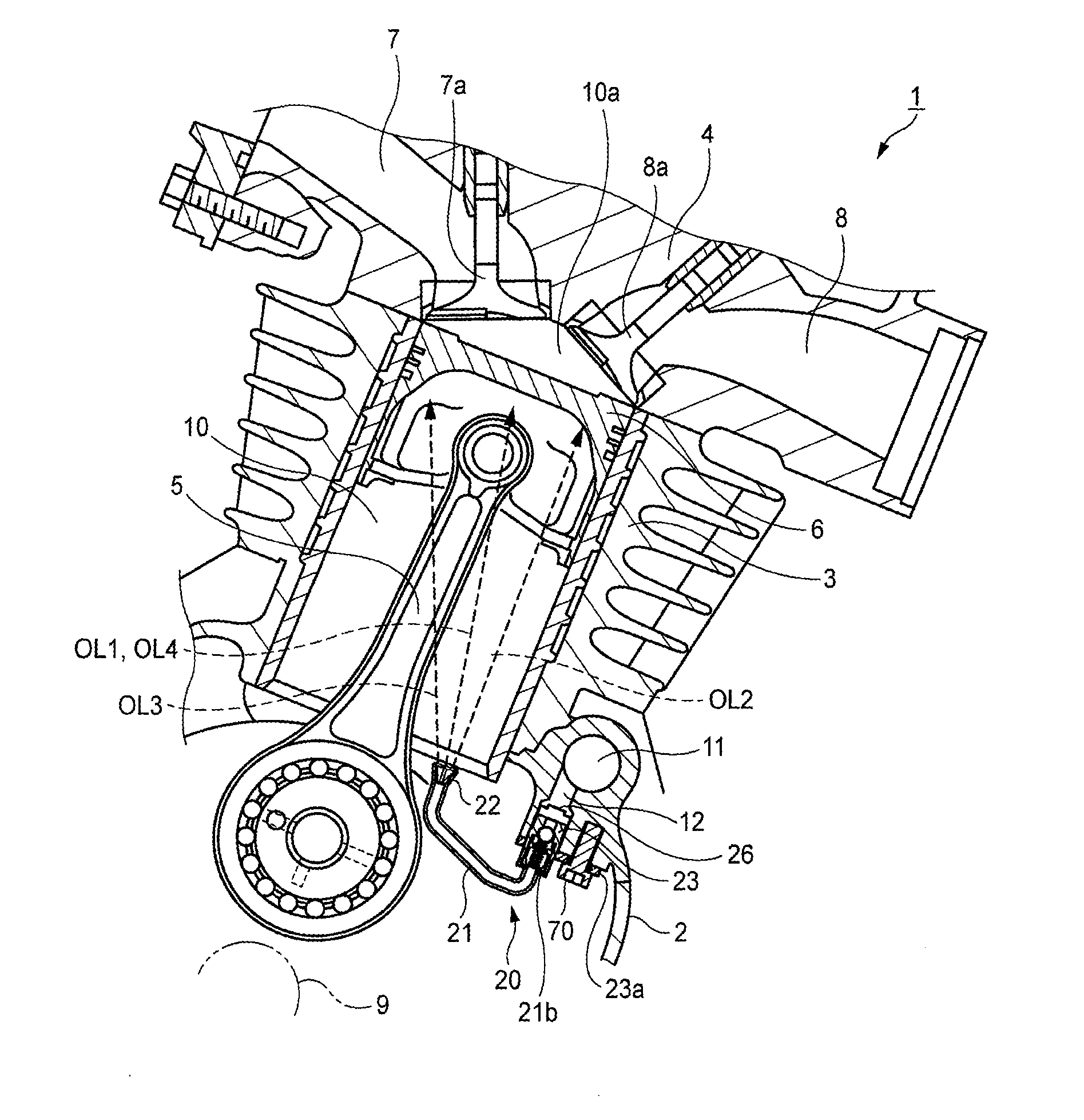
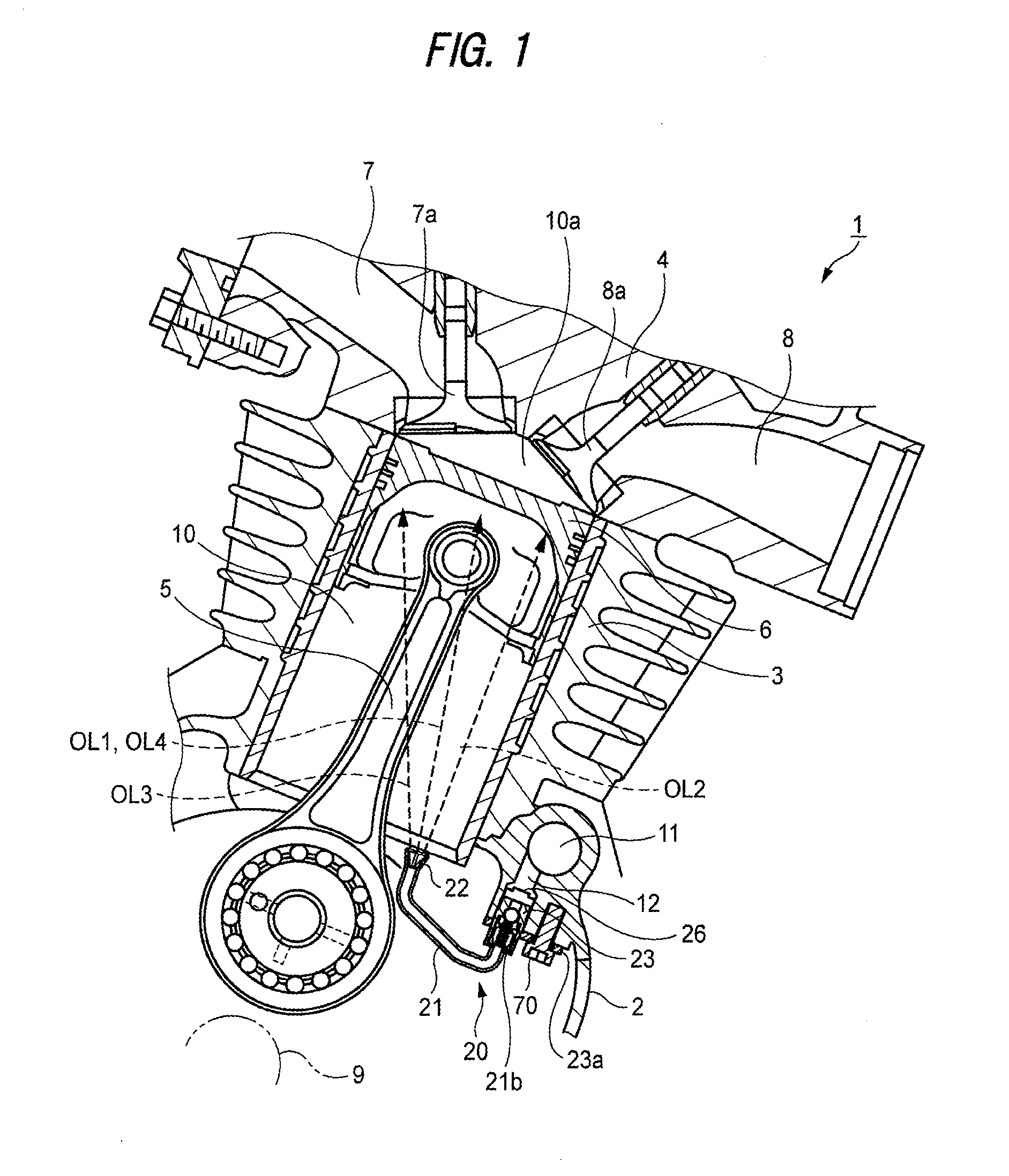
[0038]In a first embodiment of the invention, description is given specifically of an apparatus for cooling a piston of an internal combustion engine applied to a motorcycle as an example of a saddle type vehicle with reference to FIGS. 1 to 6. Here, directions such as vertical and horizontal directions in this specification are defined as directions obtained when the accompanying drawings are viewed according to the reference numerals and signs of the specification.
[0039]In an internal combustion engine 1 according to this embodiment, as shown in FIG. 1, a cylinder bore 10 is defined by a cylinder 3 and a cylinder head 4 respectively disposed above a crank case 2. To a piston 6 movable vertically within the cylinder bore 10, from behind, there is connected a connecting rod 5 which is connected to a crankshaft 9.
[0040]Here, a suction port 7 and an exhaust port 8 are connected to a combustion chamber 10a surrounded by the upper surface of the piston 6 and cylinder bore 10, whereby su...
second embodiment
[0066]Now, description is given below of a second embodiment with reference to FIG. 8.
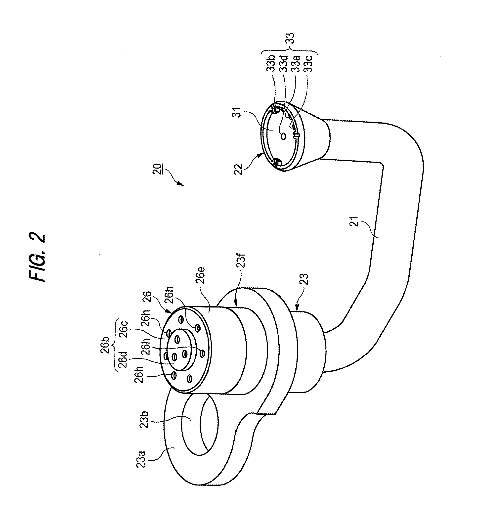
[0067]In a piston cooling apparatus 20B according to the second embodiment of the invention, while the illustration and description of the same structures of the apparatus 20B as the above-mentioned first embodiment are omitted, there are illustrated only the structures thereof and their peripheral structures different from the first embodiment. Here, FIG. 8 is an exploded perspective view of the piston cooling apparatus 20B of the second embodiment.
[0068]The filter 26B of the piston cooling apparatus 20B shown in FIG. 8, similarly to the first embodiment, has a bottomed cylindrical shape. However, in this embodiment, a female screw section 26j is formed in the inner surface of outer peripheral portion 26e. On the other hand, in the main body 23, a male screw section 23j is formed in the outer wall portion 26e. When the male screw portion 23j and female screw portion 26j are threadedly engaged with...
third embodiment
[0071]Now, description is given below of a third embodiment of the invention with reference to FIG. 9.
[0072]In a piston cooling apparatus 20C according to the third embodiment of the invention as well, while the illustration and description of the same structures of the apparatus 20C as the above-mentioned first embodiment are omitted, there are illustrated only the structures thereof and their peripheral structures different from the first embodiment. Here, FIG. 9 is an exploded perspective view of the piston cooling apparatus 20C of the third embodiment.
[0073]As shown in FIG. 9, the filter 26C of the piston cooling apparatus 20C, similarly to the first embodiment, has a bottomed cylindrical shape. However, in this embodiment, inside the outer peripheral portion 26e, there are disposed a pair of engaging pieces 26t which respectively project in a direction crossing an axial line CL. Also, the main body 23 includes in its outer wall portion 23f a pair of engaging groove portions 23g...
PUM
| Property | Measurement | Unit |
|---|---|---|
| Diameter | aaaaa | aaaaa |
| Shape | aaaaa | aaaaa |
| Distance | aaaaa | aaaaa |
Abstract
Description
Claims
Application Information
 - R&D
- Intellectual Property
- Life Sciences
- Materials
- Tech Scout
- Unparalleled Data Quality
- Higher Quality Content
- 60% Fewer Hallucinations
Browse by: Latest US Patents, China's latest patents, Technical Efficacy Thesaurus, Application Domain, Technology Topic, Popular Technical Reports.
© 2025 PatSnap. All rights reserved.Legal|Privacy policy|Modern Slavery Act Transparency Statement|Sitemap|About US| Contact US: help@patsnap.com


