User interface device providing for improved cooling of the skin

Active Publication Date: 2015-02-12
KONINKLIJKE PHILIPS ELECTRONICS NV
View PDF25 Cites 12 Cited by
  • Summary
  • Abstract
  • Description
  • Claims
  • Application Information

AI Technical Summary

Benefits of technology

[0005]Accordingly, it is an object of the present invention to provide a user interface device that overcomes the shortcomings of conventional user interface device. This object is achieved accord

Problems solved by technology

This problem is significant because such masks are typically worn for an extended period of time.
Such extended use can create several discomfort problems for the user, such as the formation of red marks o

Method used


Image

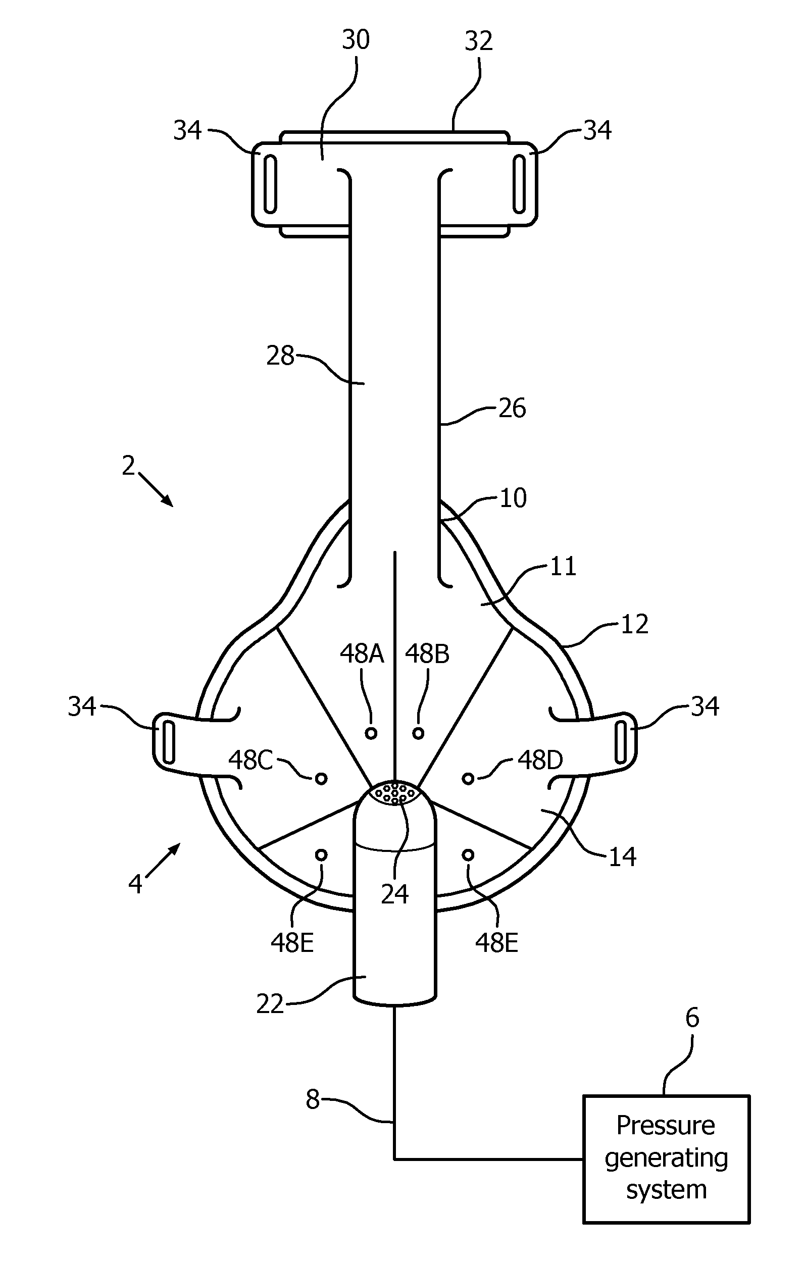
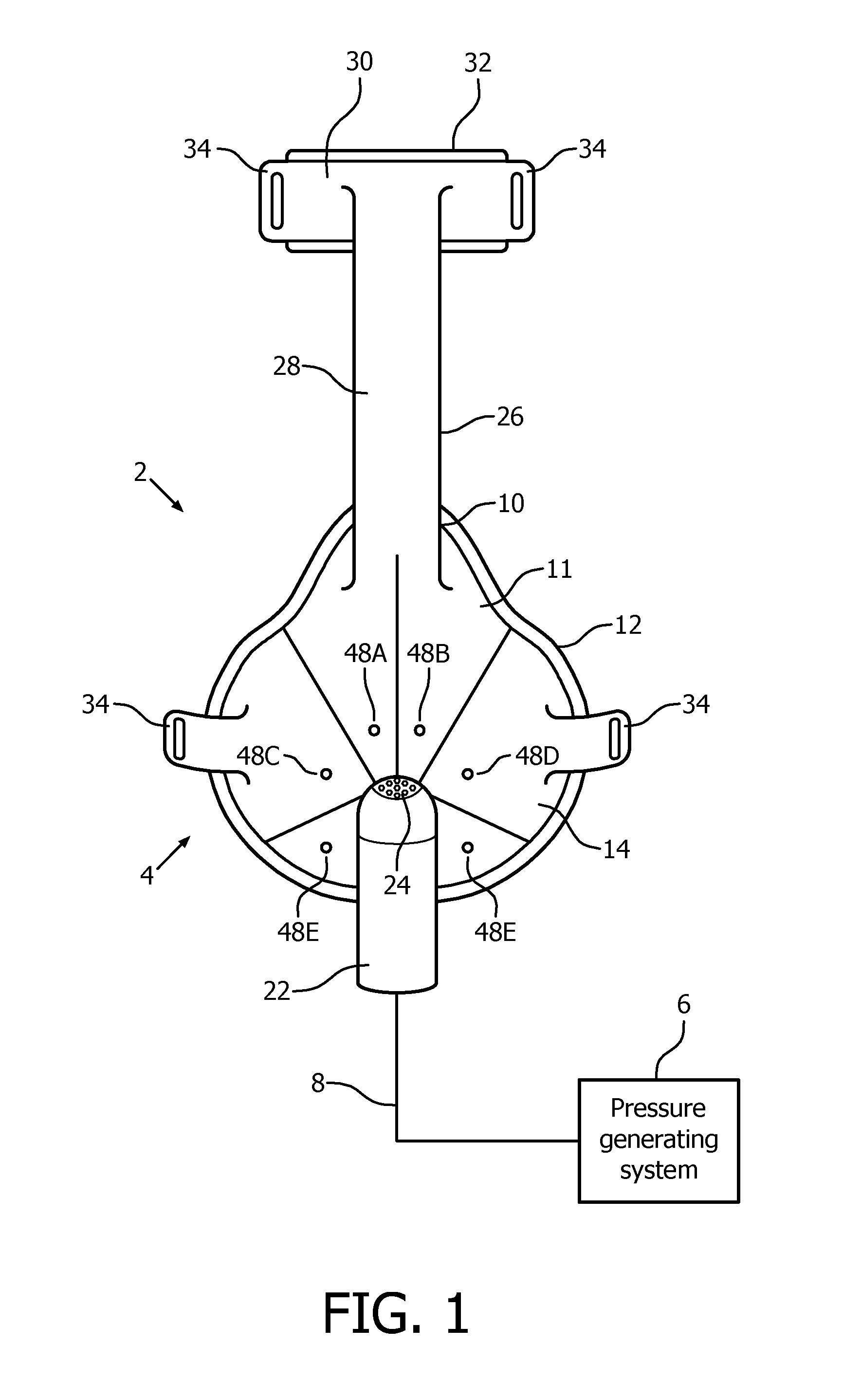
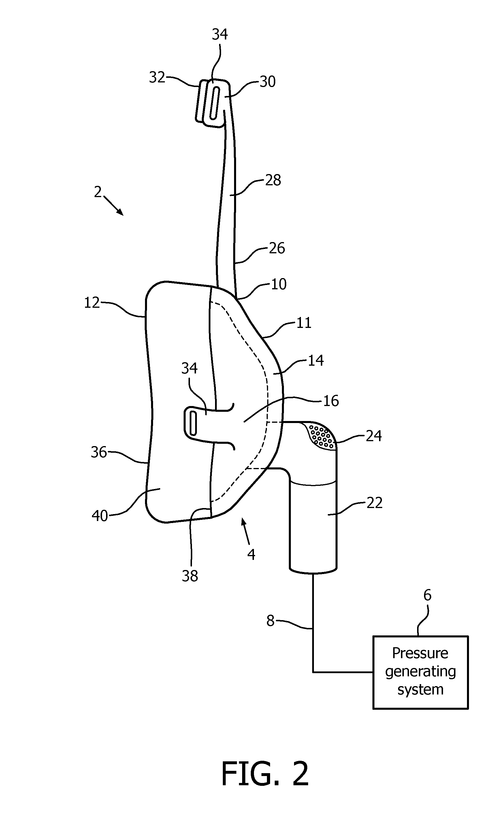
  • User interface device providing for improved cooling of the skin
  • User interface device providing for improved cooling of the skin
  • User interface device providing for improved cooling of the skin

Examples


Embodiment Construction

[0023]As used herein, the singular form of “a”, “an”, and “the” include plural references unless the context clearly dictates otherwise. As used herein, the statement that two or more parts or components are “coupled” shall mean that the parts are joined or operate together either directly or indirectly, i.e., through one or more intermediate parts or components, so long as a link occurs. As used herein, “directly coupled” means that two elements are directly in contact with each other. As used herein, “fixedly coupled” or “fixed” means that two components are coupled so as to move as one while maintaining a constant orientation relative to each other.

[0024]As used herein, the word “unitary” means a component is created as a single piece or unit. That is, a component that includes pieces that are created separately and then coupled together as a unit is not a “unitary” component or body. As employed herein, the statement that two or more parts or components “engage” one another shal...


PUM

PropertyMeasurementUnit
Lengthaaaaaaaaaa
Fractionaaaaaaaaaa
Fractionaaaaaaaaaa

Abstract

A number of user interface device embodiments are disclosed that provide for increased cooling of the skin covered by the mask and/or increased flushing of gasses, including CO2, from the mask.

Description

FIELD OF THE INVENTION[0001]The present invention relates to user interface devices for transporting a gas to and / or from an airway of a user, and in particular, to a user interface device including a mechanism for providing improved cooling of the skin covered by the user interface device.DESCRIPTION OF THE RELATED ART[0002]A variety of respiratory masks are known that have flexible seals and cover the nose, mouth, or both of a human user. The seals, which are also commonly referred to as cushions, are intended to create a seal against the user's face. Because of the sealing effect that is created, gases can be provided at a positive pressure within the mask for delivery to the airway of the user. Such seals are typically coupled to a rigid or semi-rigid shell or frame member which provides support for the mask.[0003]The uses for such masks range from high altitude breathing, i.e., aviation applications, to mining and fire fighting applications, to various medical diagnostic and th...

Claims


Application Information

Patent Timeline
IPC IPC(8): A61F7/10A61M16/06A61M16/00
CPCA61F7/10A61M16/0057A61M16/0622A61F2007/0003A61M2016/0661A61M2205/05A61M2205/3606A61M2207/00A61F2007/0061A61M16/06A61M2205/02A61M2205/362A61M16/0616A61M16/0633A61M16/0605Y10T29/49A61M2202/0225A61M2202/0085
Inventor WILLARD, NICOLAAS PETRUSHENDRIKS, CORNELIS PETRUSPOTZE, WILLEMVONCKEN, RUDOLF MARIA JOSEFASVADI, SIMAVAN ZANTEN, JOYCEKLEE, MAREIKE
Owner KONINKLIJKE PHILIPS ELECTRONICS NV
Why Eureka
Try Eureka