Liquid ejecting head and liquid ejecting apparatus

Active Publication Date: 2015-02-12
SEIKO EPSON CORP
View PDF1 Cites 17 Cited by
  • Summary
  • Abstract
  • Description
  • Claims
  • Application Information

AI Technical Summary

Benefits of technology

[0011]An advantage of some aspects of the invention is to provide a liquid ejecting head in which a compliance portion is prevented from adh

Problems solved by technology

However, there is a possibility that the film may be bent during manufacturing processes, such as a process for adhering the film which constitutes the compliance portion and the bent film may be adhered to another member (a cap member) which forms a space between the compliance portion and the member, due to dew condensation or the like.
Thus, there is a problem in that the compliance

Method used


Image

  • Liquid ejecting head and liquid ejecting apparatus
  • Liquid ejecting head and liquid ejecting apparatus
  • Liquid ejecting head and liquid ejecting apparatus

Examples


Example

Embodiment 1

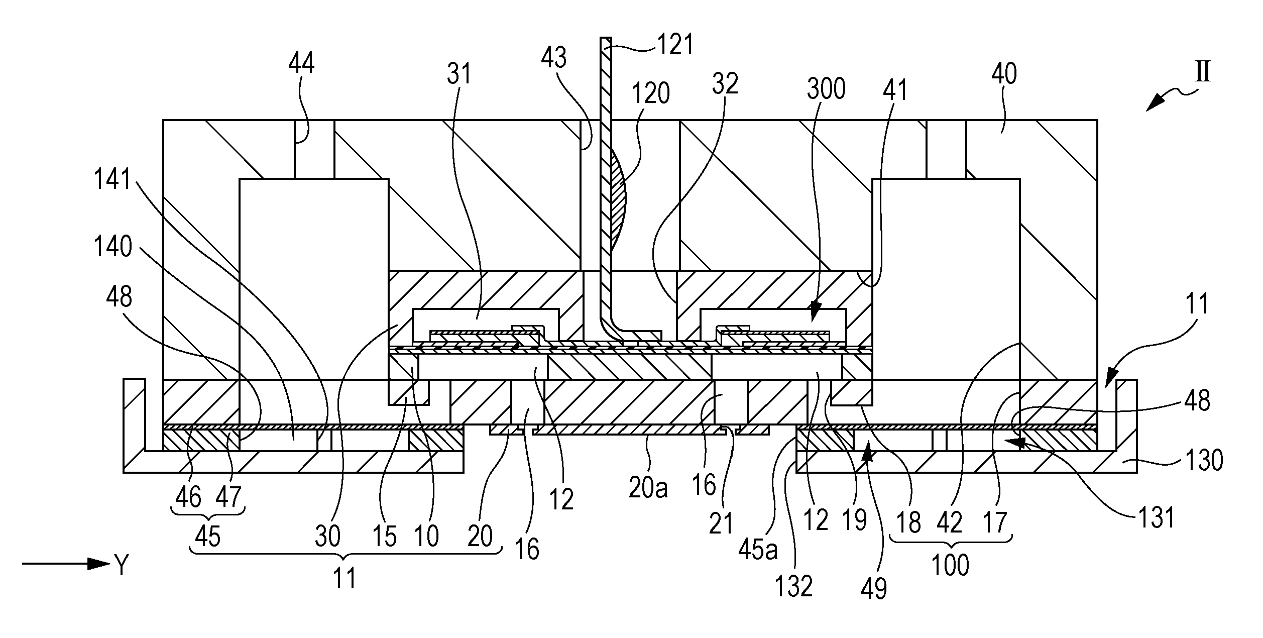
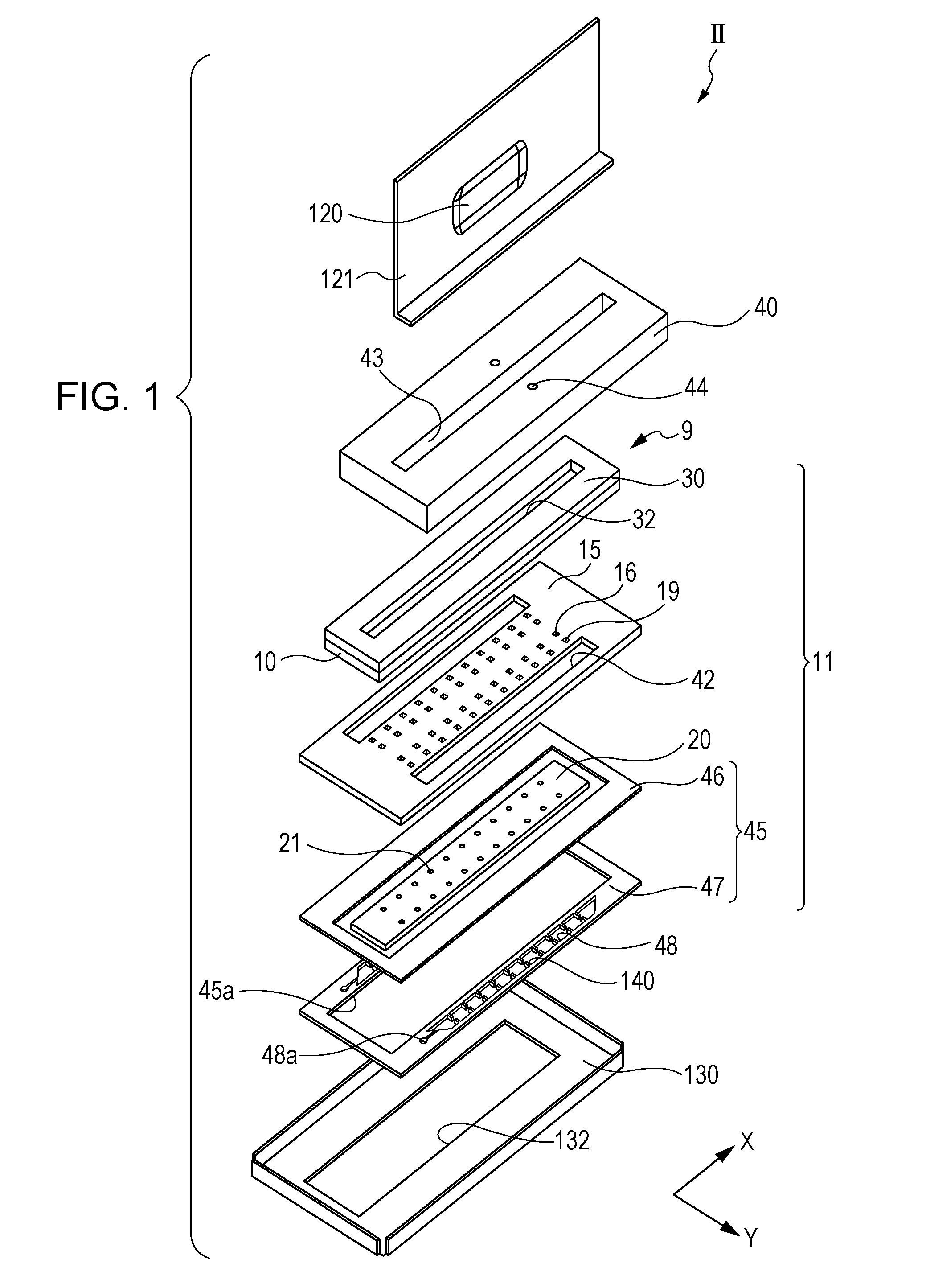
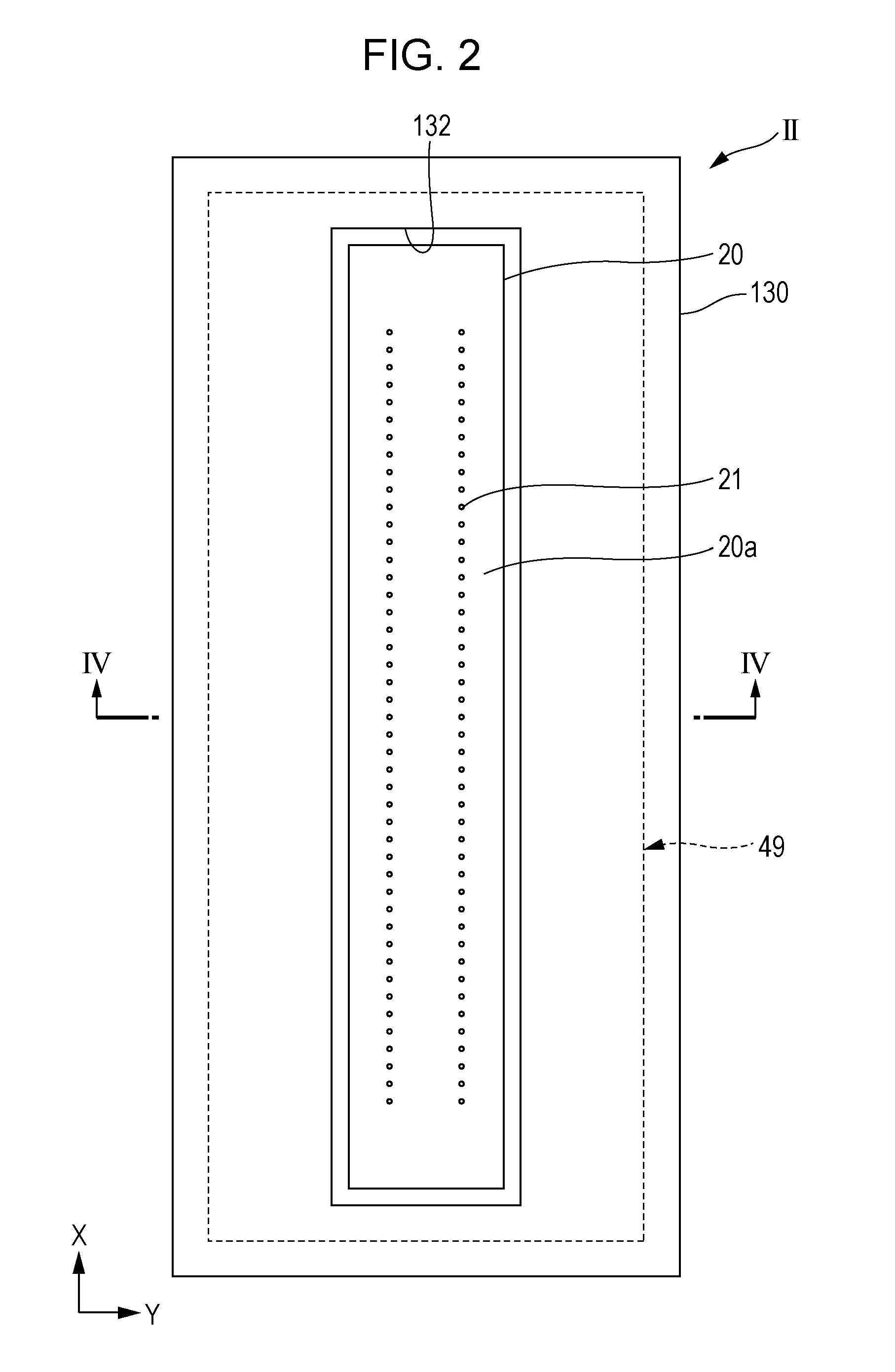
[0059]FIG. 1 is an exploded perspective view of an ink jet type recording head as an example of a liquid ejecting head according to Embodiment 1 of the invention. FIG. 2 is a plan view of the ink jet type recording head. FIG. 3 is a plan view of a compliance substrate and FIG. 4 is a cross-sectional view taken along line IIII-IIII in FIG. 2. FIG. 5 is an enlarged cross-sectional view of a principal portion of FIG. 4.

[0060]An ink jet type recording head II (hereinafter, simply referred to as a recording head II) of Embodiment 1 includes a plurality of members, such as a head main body 11, a case member 40 which is fixed to one surface side of the head main body 11, and a cover head 130 which is fixed to the other surface side of the head main body 11, as illustrated in the accompanying drawings. The head main body 11 of Embodiment 1 includes a flow-path forming substrate 10, a communication plate 15 which is provided on one surface side of the flow-path forming substrate ...

Example

Embodiment 2

[0098]FIG. 8 is a plan view illustrating a compliance substrate according to Embodiment 2 of the invention. In addition, the same reference numerals and letters are given to the same members as those in Embodiment 1, and the same descriptions as those in Embodiment 1 will not be repeated.

[0099]Protrusion portions 140A which regulate adhering of the compliance portion 49 to the cover head 130 are provided in the space 131 formed in a portion between the compliance portion 49 and the cover head 130, as illustrated in FIG. 8.

[0100]The protrusion portions 140A of Embodiment 2 are provided to protrude, in the second direction Y, from an opening edge portion of the opening portion 48 provided in the fixing substrate 47, to an area facing the manifold 100. In Embodiment 2, the protrusion portions 140A protrude, in the second direction Y, from both sides of the opening edge portion of the opening portion 48 in the second direction Y, toward a central portion. Furthermore, a plur...

Example

Embodiment 3

[0102]FIG. 9 is a plan view illustrating a compliance substrate according to Embodiment 3 of the invention. FIG. 10 is an enlarged cross-sectional view of a principal portion of an ink jet type recording head as an example of a liquid ejecting head according to Embodiment 3 of the invention. In addition, the same reference numerals and letters are given to the same members as those in Embodiments 1 and 2, and the same descriptions as those in Embodiments 1 and 2 will not be repeated.

[0103]A protrusion portion 140B which regulates adhering of the compliance portion 49 to the cover head 130 is provided in the space 131 formed in a portion between the compliance portion 49 and the cover head 130, as illustrated in FIGS. 9 and 10.

[0104]The protrusion portion 140B of Embodiment 3 is provided to protrude, in the second direction Y, from an opening edge portion of the opening portion 48 provided in the fixing substrate 47, to an area facing the manifold 100. In Embodiment 3, th...


PUM


Abstract

Provided is a liquid ejecting head that includes a manifold which communicates with a plurality of nozzle openings through which liquid is ejected, a compliance portion which constitutes a part of the manifold and is constituted by a film having flexibility, a fixing plate which is fixed to a surface side of the film, which is a side opposite to the manifold, and has an opening formed in an area which constitutes the compliance portion, and a cap member which is fixed to a surface side of the fixing plate, which is a side opposite to the compliance portion, and covers the opening, in which a protrusion portion which regulates adhering of the film to the cap member is provided, in a state where the protrusion portion is not fixed to the fixing plate, in a space formed in a portion between the compliance portion and the cap member.

Description

CROSS REFERENCES TO RELATED APPLICATIONS[0001]This application claims priority to Japanese Patent Application No. 2013-167008 filed on Aug. 9, 2013, and Japanese Patent Application No. 2014-035787 filed on Feb. 26, 2014. The entire disclosure of Japanese Patent Application Nos. 2013-167008 and 2014-035787 are hereby incorporated herein by reference.BACKGROUND[0002]1. Technical Field[0003]The present invention relates to a liquid ejecting head in which liquid is ejected through nozzle openings and a liquid ejecting apparatus, and particularly, relates to an ink jet type recording head which discharges ink as liquid and an ink jet type recording apparatus.[0004]2. Related Art[0005]Examples of an ink jet type recording head as a representative example of a liquid ejecting head which ejects liquid droplets include an ink jet type recording head which has nozzle openings and a flow path, such as a pressure generation chamber, communicating with the nozzle openings and in which ink drople...

Claims


Application Information

Patent Timeline
IPC IPC(8): B41J2/165
CPCB41J2/16505B41J2/14233B41J2/055B41J2002/14419B41J2002/14491
Inventor FUKUZAWA, YUMAOGUCHI, SATOSHIOKUI, HIROAKI
Owner SEIKO EPSON CORP
Why Eureka
Try Eureka