Laundry treating appliance with a static tub and a water trap vapor seal

a technology of static tub and laundry machine, which is applied in the direction of washing machine with receptacles, textiles and papermaking, other washing machines, etc., can solve the problems of reducing the service life of the laundry machin

Active Publication Date: 2015-02-26
WHIRLPOOL CORP
View PDF5 Cites 13 Cited by
  • Summary
  • Abstract
  • Description
  • Claims
  • Application Information

AI Technical Summary

Benefits of technology

[0005]A washing machine may include a static wash tub, a rotatable vertical axis wash basket in the static wash tub, and a drive motor for rotating the wash basket. A closure may direct wash liquid from the wash basket to a catch basin. A flange may be attached to the closure so that an unattached edge ends within the catch basin. The unattached edge may end below the surface of a first volume of wash liquid to minimize migration of wash liquid and / or vapor from the washing machine. The unattached edge may end above the surface of a second volume of wash liquid less than the first volume to minimize agitation of wash liquid in the catch basin.

Problems solved by technology

During the operation of the vertical axis washing machine with the suspended tub, the laundry load may be limited by the wash basket size, which is limited by the adjacent suspending tub.
In case the laundry is non-uniformly distributed in the wash basket, an unbalance during the rotation of the wash basket may cause it to deviate off an anticipated rotational orbit, and in extreme cases induce collisions between the wash basket and the tub and / or the tub and the cabinet, based upon the selected basket / tub / cabinet design, such that spin extraction efficiency may be limited.
While the static tub is beneficial in that it can aid in increasing the capacity of the washing machine, the wash liquid and vapor sealing apparatus may be more costly than non-static tub washing machines.
Moreover, the wash liquid and vapor sealing apparatus may also be difficult to incorporate into washing machine components, may have a shorter life cycle than the non-static tub washing machines, and may also interact with the suspension systems, which may contribute to instability, vibration, and noise.

Method used


Image

  • Laundry treating appliance with a static tub and a water trap vapor seal
  • Laundry treating appliance with a static tub and a water trap vapor seal
  • Laundry treating appliance with a static tub and a water trap vapor seal

Examples


first embodiment

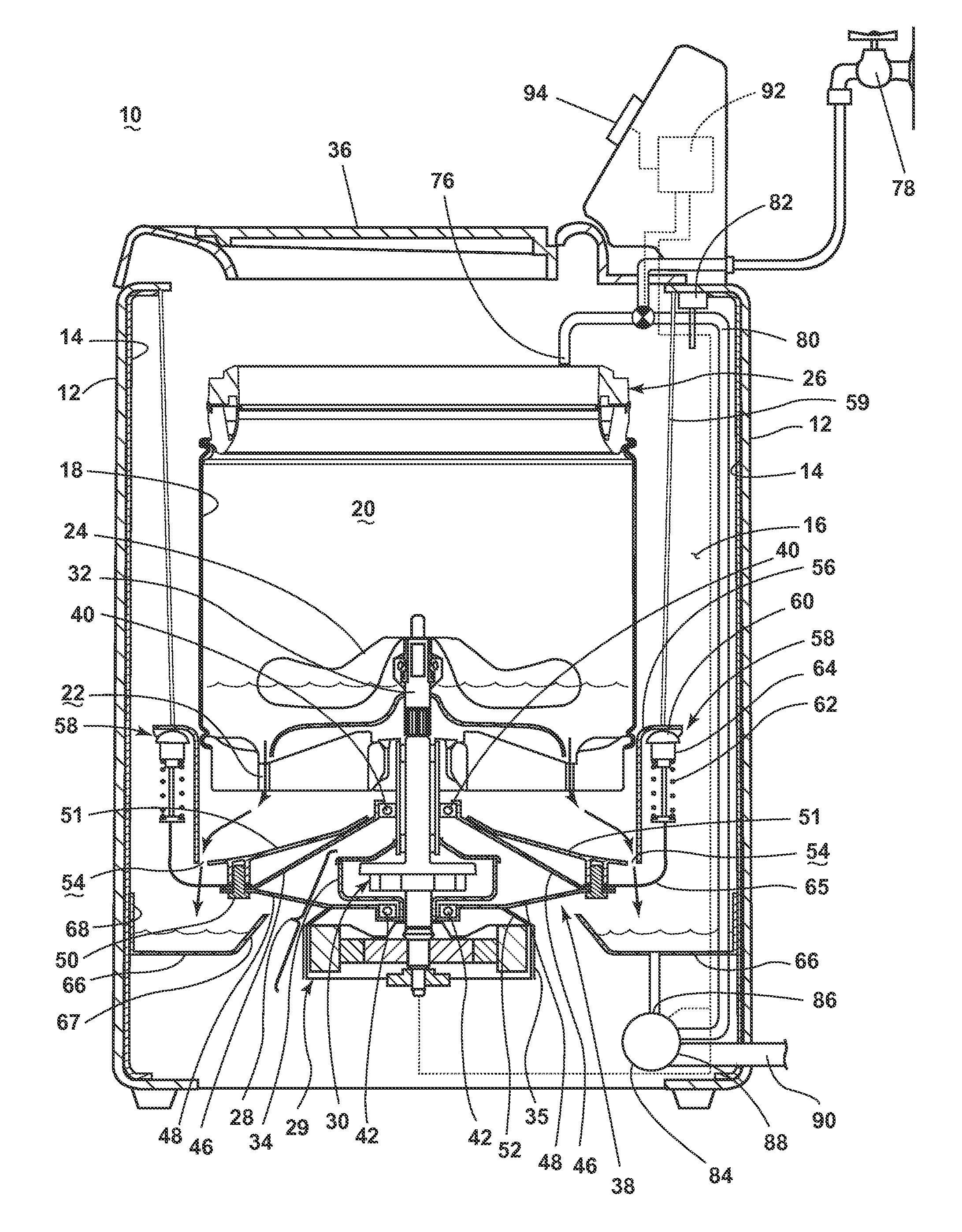
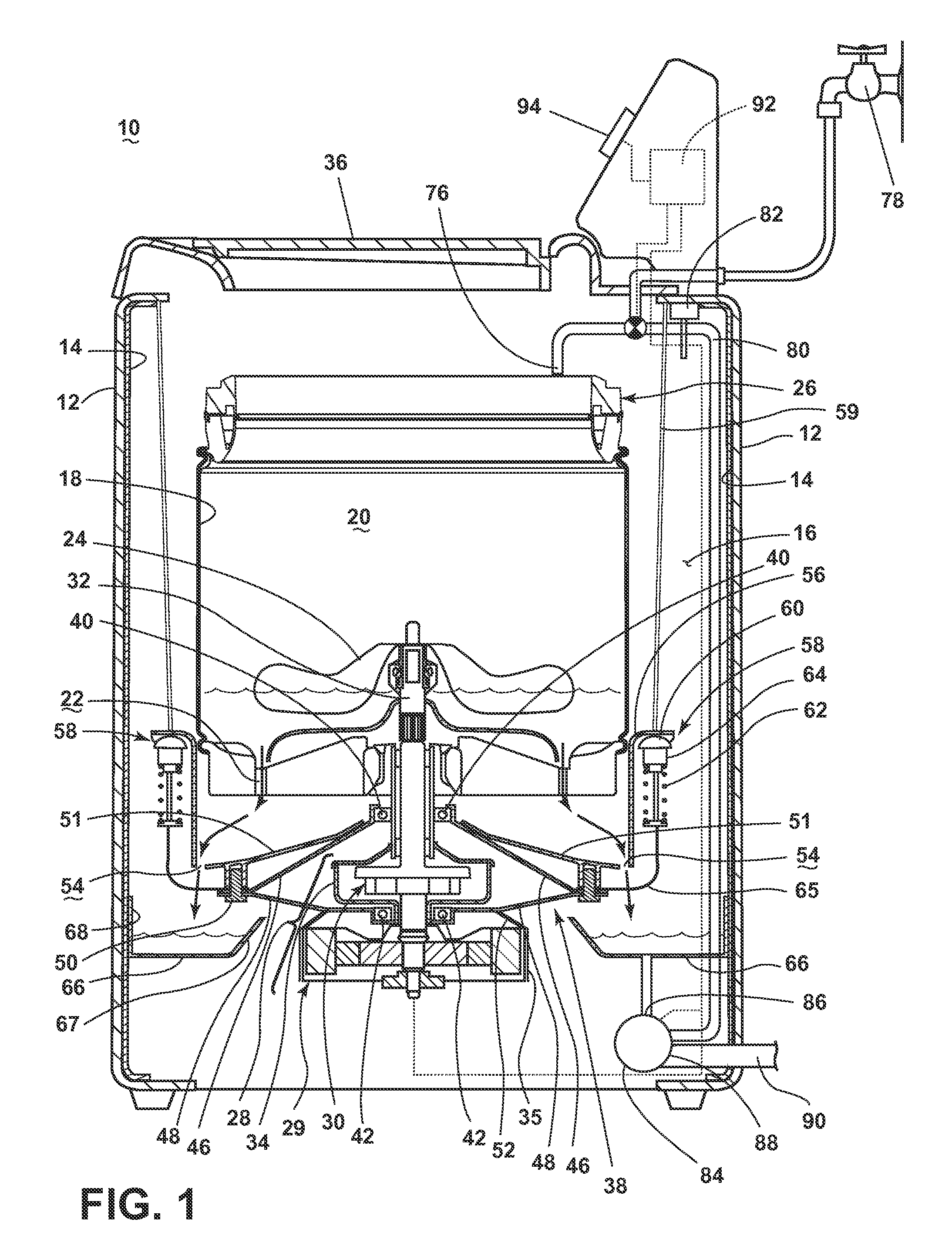
[0013]Referring now to the drawings, FIG. 1 is a schematic view of an exemplary laundry treating appliance 10 in the form of a washing machine according to the invention. While the laundry treating appliance 10 is illustrated as a vertical axis, top-fill washing machine, the invention may have applicability in other laundry treating appliances, such as a horizontal axis washing machine, a combination laundry treating appliance and dryer, an extractor, a non-aqueous laundry treating appliance, and a tumbling or stationary refreshing / revitalizing machine, for example.

[0014]The washing machine 10 may include a cabinet or housing 12, and a static wash tub 14 which is in fixed position with respect to the cabinet 12. In one example, as illustrated in FIG. 1, the static wash tub 14 may be integrated to the cabinet 12, and define an interior 16 of the washing machine 10. By “static wash tub,” it is not necessarily meant that the tub is fixedly integrated to the cabinet 12. Alternately, the...

second embodiment

[0049]Referring to FIG. 3, a schematic cross-sectional view of a laundry treating appliance with a static wash tub according to the invention is illustrated wherein the laundry treating appliance is in the wash phase.

[0050]The primary difference between the first embodiment in FIG. 1 and the second embodiment in FIG. 3 may be a flange 102 mounted to the closure 51. As illustrated, the flange 102 may be coupled to a low end portion of the closure 51 such that the flange 102 may extend downwardly from the low end portion of the closure 51 until one end portion of the flange 102 contacts the bottom of the catch basin 66 during the wash phase.

[0051]The flange 102 may be configured to form a seal when the flange 102 contacts the bottom of the catch basin 66. As a result, the flange 102 may act as a trap for confining the wash liquid and / or vapor inside the interior 16 of the static wash tub 14. For example, the flange 102 may form a trap seal with the bottom of the catch basin 66 for blo...

third embodiment

[0052]FIG. 4 is a schematic cross-sectional view of the laundry treating appliance of FIG. 3 according to the invention, where the laundry treating appliance in FIG. 4 is in a spin extraction phase. When the wash phase is complete, the wash liquid may be drained out of the catch basin 66, followed by the spin extraction phase where the wash basket 18 rotates at a high spin speed.

[0053]It is understood that, during the high speed spin extraction phase, the wash basket 18 may be subject to a translational and / or vertical movement from any unbalance of non-uniformly distributed laundry items in the wash basket 18. The translational and / or vertical movement of the wash basket 18 may be transmitted to other coupled components in the form of vibration. In one example, vibration may transmit to the bearing housing 38, the flange 102, the flexure element 65, and the suspension system 58.

[0054]The suspension system 58 may move horizontally and / or vertically for damping out the vibrations of ...


PUM


Abstract

A washing machine may include a static wash tub, a rotatable vertical axis wash basket in the static wash tub, and a drive motor for rotating the wash basket. A closure may direct wash liquid from the wash basket to a catch basin. A flange may be attached to the closure so that an unattached edge ends within the catch basin. The unattached edge may end below the surface of a first volume of wash liquid to minimize migration of wash liquid and / or vapor from the washing machine. The unattached edge may end above the surface of a second volume of wash liquid less than the first volume to minimize agitation of wash liquid in the catch basin.

Description

CROSS-REFERENCE TO RELATED APPLICATION[0001]This application is a continuation-in-part, and claims the benefit of, U.S. application Ser. No. 13 / 970,733, filed Aug. 20, 2013, which is incorporated by reference herein in its entirety.BACKGROUND OF THE INVENTION[0002]Laundry treating appliances, such as vertical axis washing machines, typically include a cabinet, a tub in the interior of the cabinet, and a rotatable wash basket mounted in the tub that receives laundry for treatment according to a cycle of operation. The tub may suspend from the cabinet, and may be supported by one or more suspension systems.[0003]During the operation of the vertical axis washing machine with the suspended tub, the laundry load may be limited by the wash basket size, which is limited by the adjacent suspending tub. In case the laundry is non-uniformly distributed in the wash basket, an unbalance during the rotation of the wash basket may cause it to deviate off an anticipated rotational orbit, and in ex...

Claims


Application Information

Patent Timeline
Patent Type & Authority Applications(United States)
IPC IPC(8): D06F17/06D06F39/08D06F21/08
CPCD06F17/06D06F39/08D06F21/08D06F17/08D06F23/04D06F37/12D06F37/26D06F39/083D06F33/47
Inventor ERICKSON, DONALD E.SHARP, BRENNER M.
Owner WHIRLPOOL CORP
Why Eureka
Try Eureka