
Enhanced Charging Handle

a charging handle and handle technology, applied in the field of firearms, can solve the problems of improper operation, deficient ergonomics of the charging handle, etc., and achieve the effect of enhancing the charging handle, more surface area, and reliably operating the charging handl

Inactive Publication Date: 2015-02-26
BUNKER BENJAMIN
View PDF1 Cites 16 Cited by
  • Summary
  • Abstract
  • Description
  • Claims
  • Application Information

AI Technical Summary

Benefits of technology

The present invention provides an enhanced charging handle for firearms that allows users to reliably operate it. The new handle has a vertical lever with more surface area for the user's fingers, making it easier to grip even when wearing gloves or in wet or injury-related situations. The v-shaped lever design also provides more leverage to unlatch the charging handle, making it more reliable than existing charging handles. Overall, the improved design of the present invention enhances the user's ability to operate the charging handle and ensures reliability in various situations.

Problems solved by technology

These proposed changes still leave the charging handle with deficient ergonomics which can prevent the user from moving the bolt via the charging handle in high-stress situations.
The charging handle designs currently proposed can result in improper operation when the firearm user is wearing gloves, as many military and law enforcement personnel use, or when the user's hands are wet from sweat, water, mud, blood or other liquid.

Method used


Image

  • Enhanced Charging Handle
  • Enhanced Charging Handle
  • Enhanced Charging Handle

Examples


Embodiment Construction

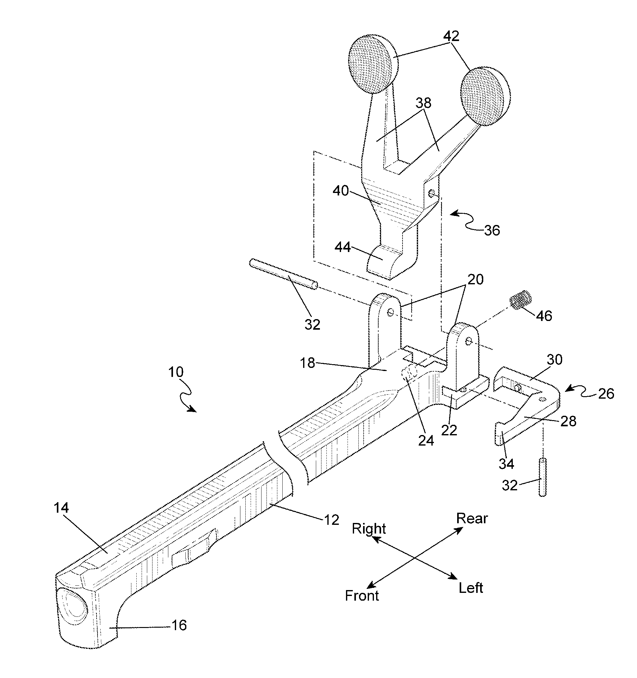
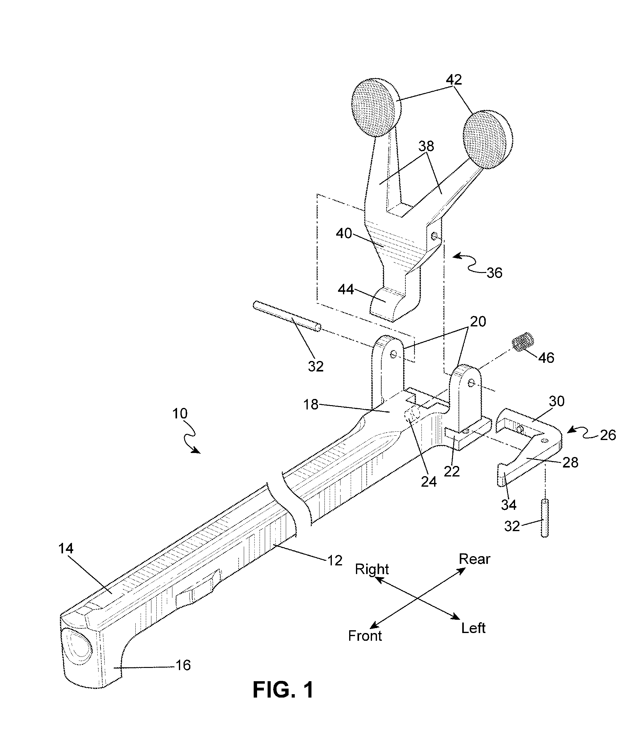
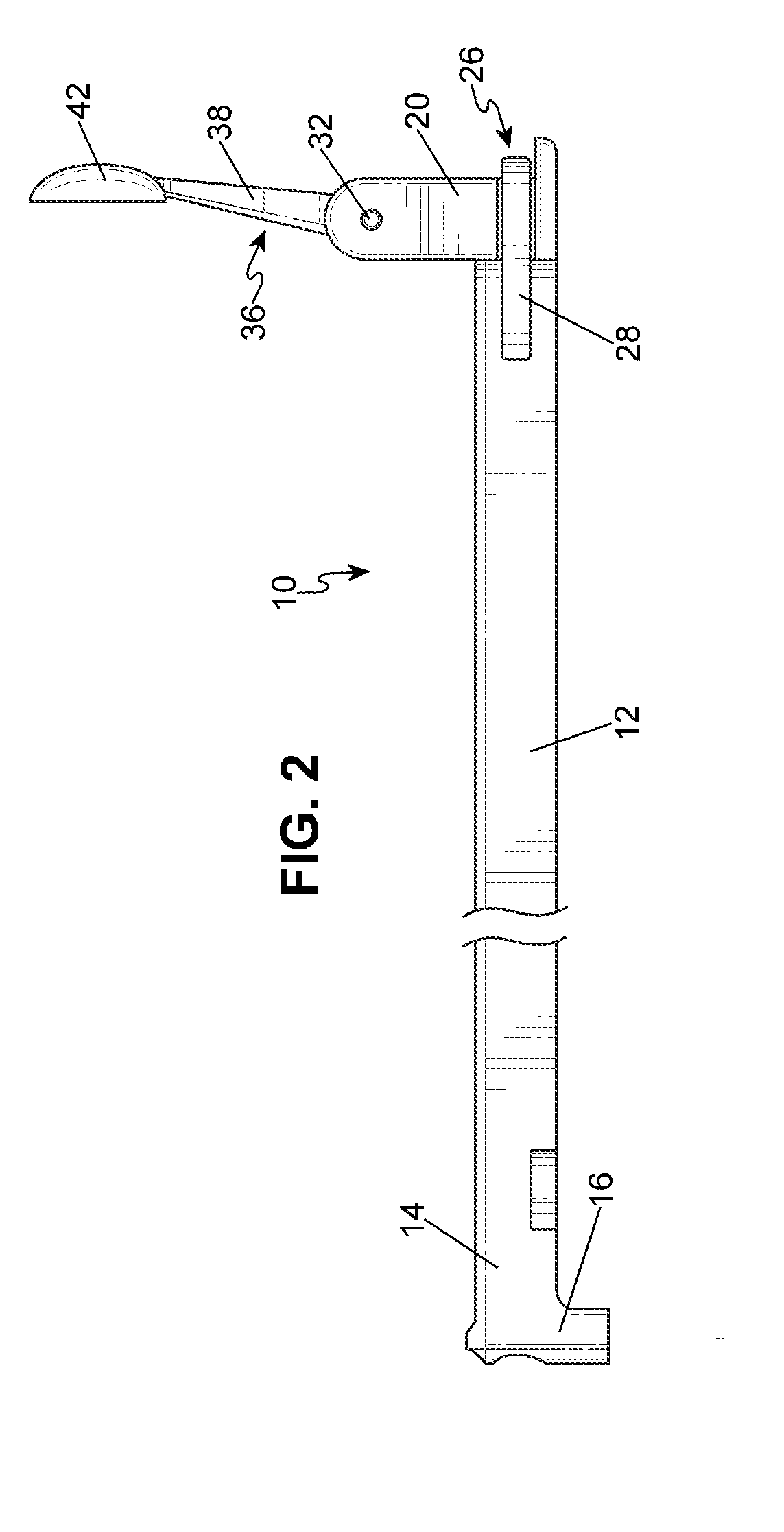
[0014]Referring to FIGS. 1, 2, and 5 the enhanced charging handle 10 has an elongated shaft 12 having a forward end 14 with a bolt hook 16 that engages the bolt carrier group (not shown). The charging handle 10 also has a rear end 18 having two parallel vertical arms 20 where one vertical arm 20 extends from the right side of the rear end 18 and the other vertical arm 20 extends from the left side of the rear end 18. The rear end 18 further has a longitudinal slot 22 on the left side and a rear-facing spring cavity 24 in the center.

[0015]Horizontally oriented within the slot 22 is an L-shaped latch 26 having a forward leg 28 and a rear leg 30. The latch 26 is pivotally attached to the rear end 18 by a vertically oriented roll pin 32 inserted through corresponding holes in the latch 26 and rear end 18. The forward leg 28 has an inward-facing tooth 34 at the distal end that can engage a lip on the upper receiver (not shown) thereby locking the charging handle 10 in the forward positio...


PUM


Abstract

An enhanced charging handle for a firearm which has an elongated shaft having a forward end and a rear end. The forward end is formed into a bolt hook that engages the bolt carrier group within the firearm. Attached to the rear end is a latching assembly comprising an L-shaped latch, a vertical lever, and a compression spring where the latch and vertical lever are pivotably attached to the rear end. The latch and vertical lever operate together such that pivoting the vertical lever disengages the latch from the upper receiver of a firearm allowing the charging handle to be moved freely by the user independent of the upper receiver of the firearm.

Description

FIELD OF THE INVENTION[0001]The present invention relates in general to firearms and more particularly to charging handles for firearms.BACKGROUND OF THE INVENTION[0002]Many modern firearms operate by utilizing a longitudinally reciprocating bolt within the firearm. A popular example of such a firearm is the M16 family of firearms which includes the AR-15. A reciprocating bolt configuration is typically contained within a receiver where it cannot be manually operated without partially disassembling the firearm. In instances where the bolt needs to be manually operated, such as moving the bolt into battery or clearing a jam or manually ejecting a cartridge, an externally accessible charging handle is employed to allow the firearm user to manually operate the bolt quickly without disassembling the firearm.[0003]The original M16 charging handle is in the general shape of a T where the longer member is inserted into the receiver with a distal end that interfaces with the internal bolt. ...

Claims


Application Information

Patent Timeline
Patent Type & Authority Applications(United States)
IPC IPC(8): F41A7/00
CPCF41A7/00F41A3/72F41A35/06
Inventor BUNKER, BENJAMIN
Owner BUNKER BENJAMIN
Learn More