Adhesive Coating Device With Discharge Adjustment Mechanism

a technology of discharge adjustment and adhesive coating, which is applied in the direction of coatings, manufacturing tools, insoles, etc., can solve the problem that the conventional adhesive coating device does not provide a mechanism for adjusting the amount of applied adhesiv

Active Publication Date: 2015-02-26
HUANG YU CHENG
View PDF3 Cites 21 Cited by
  • Summary
  • Abstract
  • Description
  • Claims
  • Application Information

AI Technical Summary

Benefits of technology

[0005]It is therefore one object of the invention to provide an adhesive coating device comprising a reservoir for containing a quantity of adhesive; opposite first and second adjustment rollers disposed at a bottom of the reservoir; a pattern roller disposed between and spaced apart from the first and second adjustment rollers and having a predetermined pattern formed thereon; a resilient roller disposed under the pattern roller; a roller member disposed under the resilient roller; pivotal, co-rotated first and second links disposed on a side of the reservoir and operatively connected to the first and second adjustment rollers respectively; a spring biased adjustment screw having a bottom end pivotably secured to an end of the first link; and each of the first and second adjustment rollers includes a scraping member, a shaft through the scraping member, and two limit

Problems solved by technology

However, these conventional adhesive coating devices are not pro

Method used


Image

  • Adhesive Coating Device With Discharge Adjustment Mechanism
  • Adhesive Coating Device With Discharge Adjustment Mechanism
  • Adhesive Coating Device With Discharge Adjustment Mechanism

Examples


Embodiment Construction

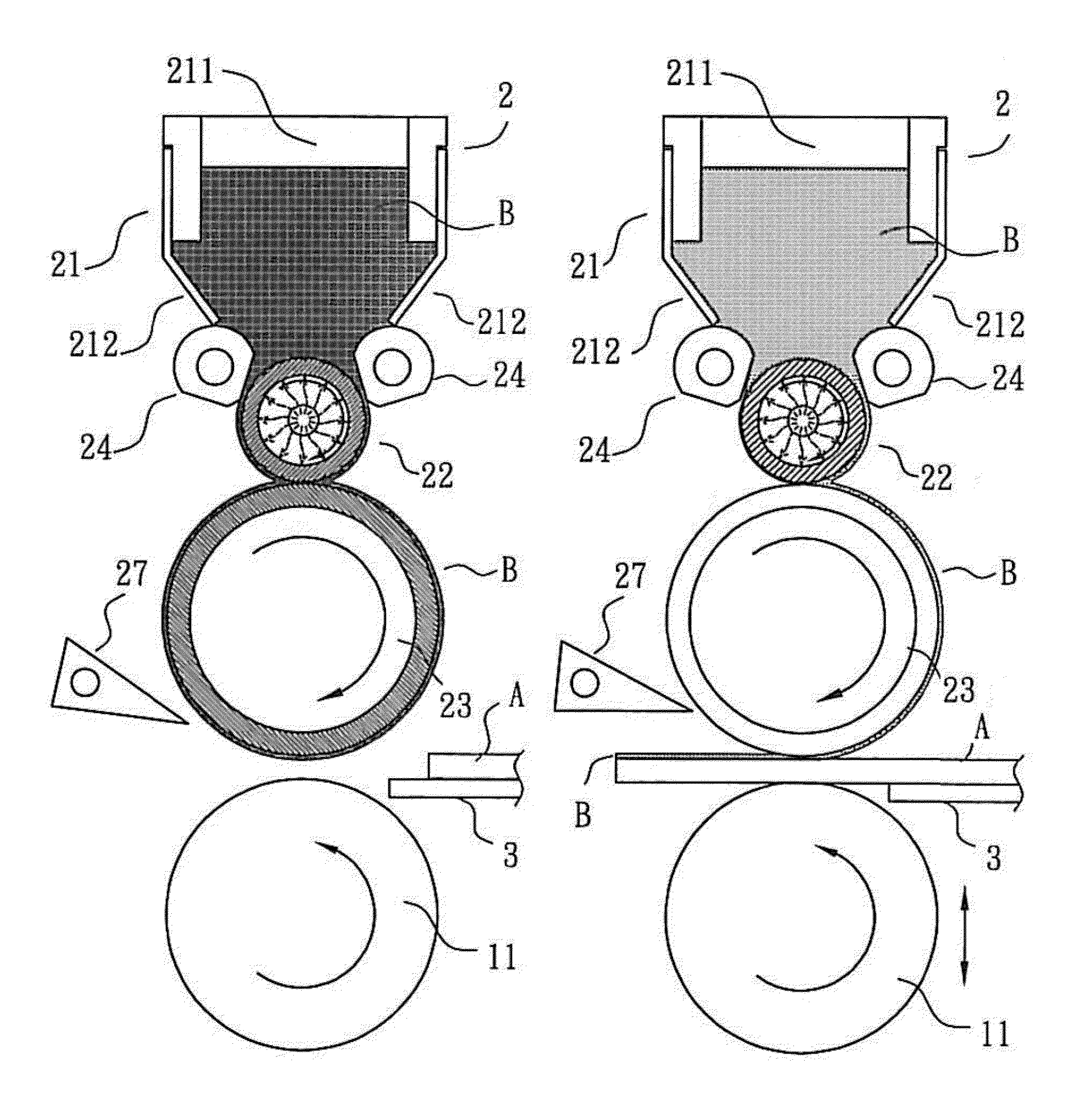
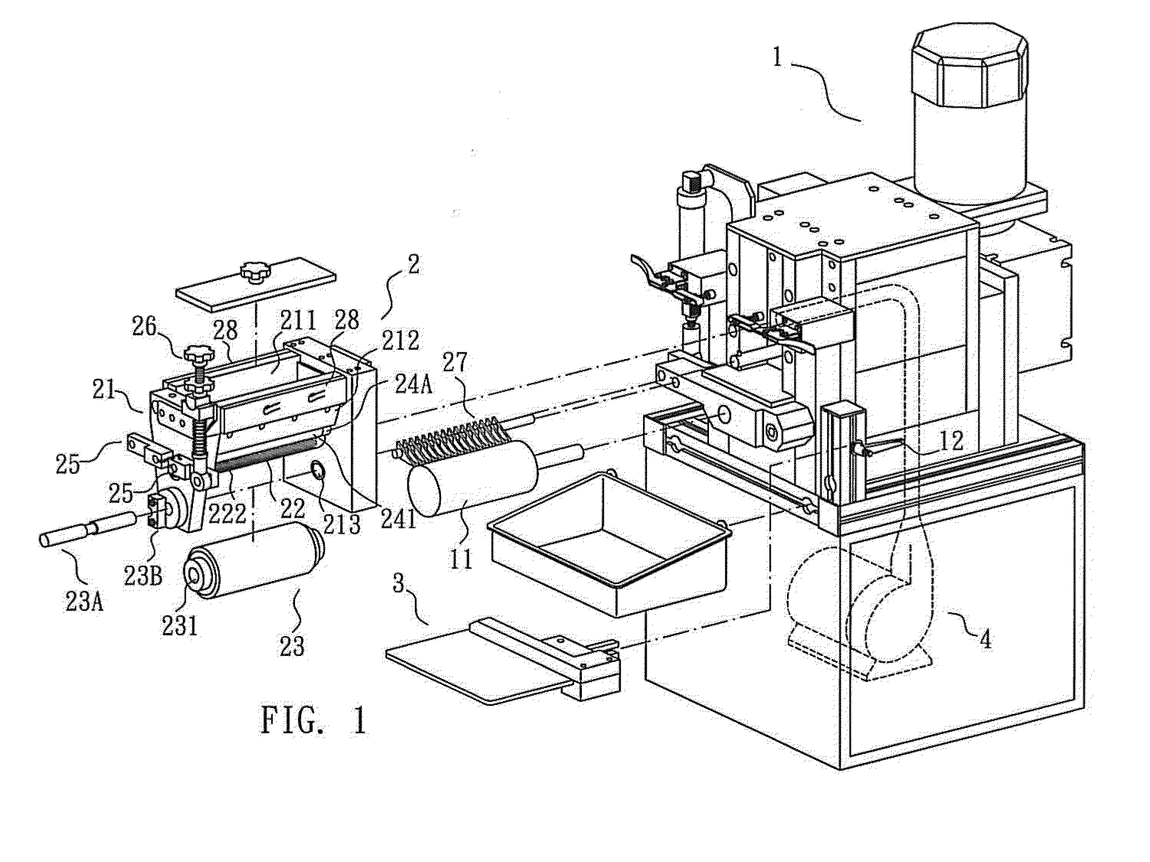
[0029]Referring to FIGS. 1 to 19, an adhesive coating device 2 in accordance with the invention is mounted on a machine 1. The adhesive coating device 2 comprises the following components as discussed in detail below.

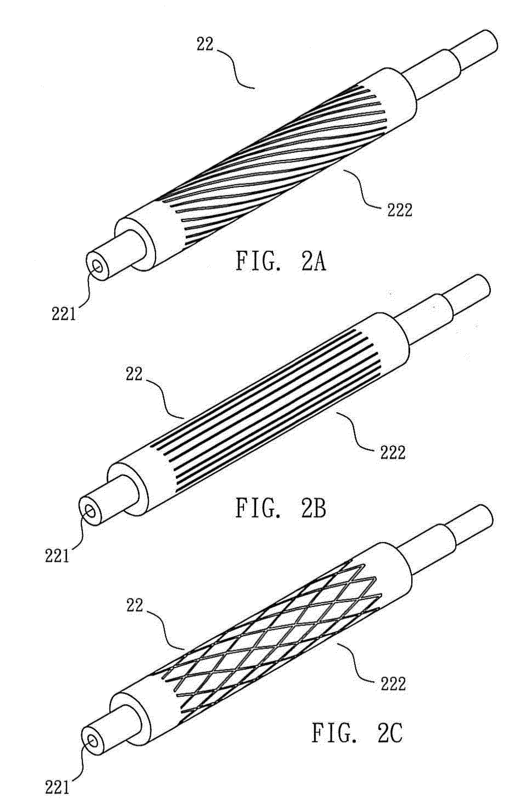
[0030]A base 21 includes two opposite end members 212, two opposite cooling members 28 provided on tops of the end members 212 respectively, and a reservoir 211 defined by the end members 212, the cooling members 28, and two sides. The reservoir 211 is adapted to contain a quantity of liquid adhesive B. Two opposite adjustment rollers 24 are provided at bottom ends of the end members 212. A pattern roller 22 includes an axial, hollow shaft 221 and a pattern 222 formed on its outer surface. The pattern 222 can be inclined lines (see FIG. 2A), straight lines (see FIG. 2B), or a net having a plurality of rhombs (see FIG. 2C). The adjustment roller 24 includes a scraping member 241, a shaft 242 through the scraping member 241, and two limit members 24A put on the shaft 242 ...


PUM


Abstract

An adhesive coating device is provided with an adhesive reservoir; two opposite adjustment rollers at bottom of the reservoir; a pattern roller between the adjustment rollers and having a pattern formed thereon; a resilient roller under the pattern roller; a roller member under the resilient roller; two pivotal, co-rotated links on a side of the reservoir and operatively connected to the adjustment rollers respectively; and a spring biased adjustment screw pivotably secured to an end of one link. Clockwise rotation of the adjustment screw rotates the links at different directions, thereby decreasing a gap between the pattern roller and each adjustment roller.

Description

BACKGROUND OF THE INVENTION[0001]1. Field of the Invention[0002]The invention relates to adhesive coating devices and more particularly to an adhesive coating device having a mechanism for adjusting amount of applied adhesive.[0003]2. Description of Related Art[0004]Adhesive coating devices are well known in the art. However, these conventional adhesive coating devices are not provided with a mechanism for adjusting amount of applied adhesive. Thus, an outer layer having a preset thickness can be formed on a surface of an article using the conventional adhesive coating device. Thus, the need for improvement still exists.SUMMARY OF THE INVENTION[0005]It is therefore one object of the invention to provide an adhesive coating device comprising a reservoir for containing a quantity of adhesive; opposite first and second adjustment rollers disposed at a bottom of the reservoir; a pattern roller disposed between and spaced apart from the first and second adjustment rollers and having a pr...

Claims


Application Information

Patent Timeline
IPC IPC(8): B05C11/00B05C21/00C09J5/00B05C1/02
CPCB05C11/00C09J5/00B05C21/00B05C1/025A43D11/03A43D25/181B05C1/02B05C1/0813B05C1/0817B05C1/083B05D5/10B27G11/00
Inventor HUANG, YU-CHENG
Owner HUANG YU CHENG
Why Eureka
Try Eureka