Composite disc brake backing plate

a disc brake and backing plate technology, applied in the direction of brake types, friction linings, braking elements, etc., can solve the problems of increasing fuel consumption and waste of valuable materials, and reducing the service life of the brak

Active Publication Date: 2015-02-26
GRIPMETAL LTD
View PDF9 Cites 35 Cited by
  • Summary
  • Abstract
  • Description
  • Claims
  • Application Information

AI Technical Summary

Benefits of technology

[0018]Preferably, the core material is selected to be heat-resistant. The core mate

Problems solved by technology

However, such pieces are very heavy, particularly in large truck applications.
This has been a recognized problem in the art.
Weight on the sprung or suspended components of a v

Method used


Image

  • Composite disc brake backing plate
  • Composite disc brake backing plate
  • Composite disc brake backing plate

Examples


Embodiment Construction

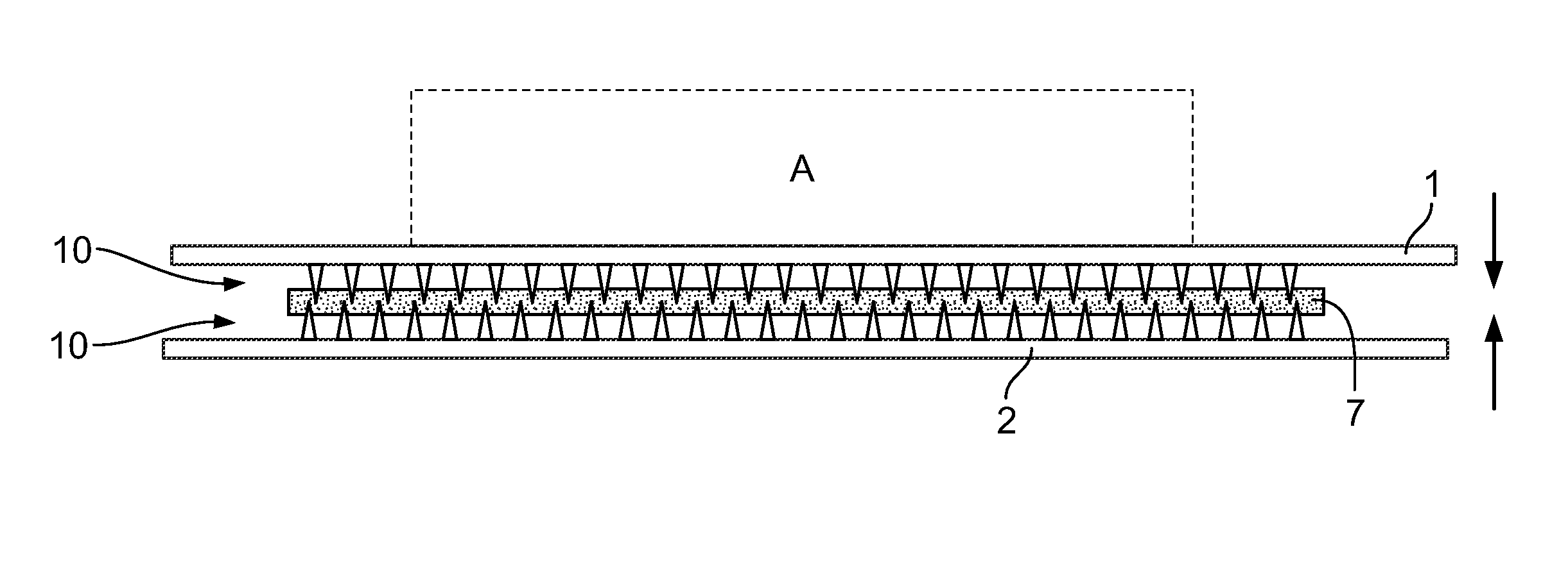
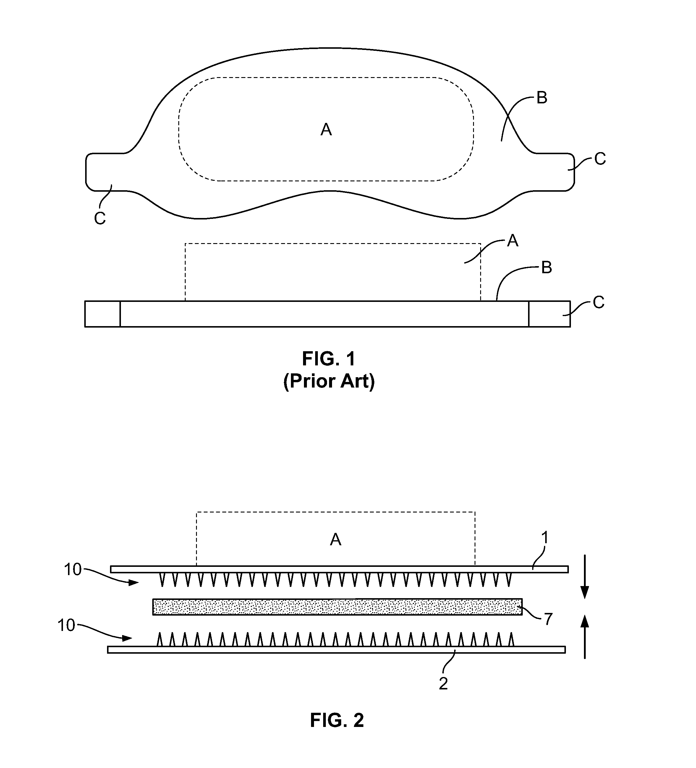
[0038]As shown in FIG. 1 (in isometric top and front views), the prior art brake pad is made up of a friction material cake A that is joined to a backing plate B.

[0039]The friction material is an ablative material that contacts the rotor in the course of braking. Friction materials are generally composite materials, whose components may include metallic, semi-metallic, inorganic (e.g. ceramic) and organic compounds. In some formulations, friction material may include particles, filaments, shavings or fibers dispersed in the material. A pre-form cake of friction material is molded onto the backing plate using a heat pressure molding system whereby the cake flows into and around various features on the backing plate. When cooled, the friction material becomes fully hard and bonded to the backing plate.

[0040]Prior art backing plates are solid, typically steel, plates that may have holes or other features for retaining friction material. There are many different shapes of backing plates...


PUM


Abstract

A brake backing plate is provided in which a non-compressible core material is sandwiched between two sheet metal stampings to make a lightweight, composite brake backing plate. Each of the stampings has a textured face with a plurality of integrally formed piercing members. By rolling or pressing, the piercing members of the textured faces are fully embedded in the core material, and thus lock the stampings and the core material together.

Description

CROSS-REFERENCE TO RELATED APPLICATIONS[0001]This application is a U.S. continuation application under 35 U.S.C. §111(a) claiming priority under 35 U.S.C. §§120 and 365(c) to International Application No. PCT / IB2013 / 002968, filed Nov. 22, 2013, which claims the priority benefit of Canadian Patent Application No. 2,798,303, filed Dec. 7, 2012, the contents of which are incorporated by reference herein in their entirety for all intended purposes.FIELD OF THE INVENTION[0002]The invention relates to backing plates for disc brake pads.BACKGROUND OF THE INVENTION[0003]Modern vehicle brake systems allow for slowing or stopping movement of the vehicle in a controlled manner. A typical automobile or light truck brake system includes a disc brake assembly for each of the front wheels and either a drum brake assembly or a disc brake assembly for each of the rear wheels. The brake assemblies are simultaneously actuated by hydraulic or pneumatic pressure generated when an operator of the vehicle...

Claims


Application Information

Patent Timeline
IPC IPC(8): F16D65/095
CPCF16D65/095F16D65/092F16D2069/0441F16D2069/0491F16D69/04F16D69/0408
Inventor ARBESMAN, RAYPHAM, NGHIMACKELVIE, WINSTON
Owner GRIPMETAL LTD
Why Eureka
Try Eureka