Systems and Methods for Restricting Fluid Flow in a Wellbore with an Autonomous Sealing Device and Motion-Arresting Structures

a wellbore and fluid flow technology, applied in the direction of fluid removal, borehole/well accessories, survey, etc., can solve the problems of increasing the difficulty and/or cost of setting the required number of isolation plugs, affecting the economic and/or efficient stimulation of the subterranean formation, and ineffective under others

Inactive Publication Date: 2015-03-05
KUMARAN KRISHNAN +4
View PDF5 Cites 8 Cited by
  • Summary
  • Abstract
  • Description
  • Claims
  • Application Information

AI Technical Summary

Benefits of technology

[0014]The methods include conveying the autonomous sealing device through the casing conduit, determining that the autonomous sealing device is located within a target portion of the casing conduit, expanding the autonomous sealing device to the expanded configuration, retaining the autonomous sealing device on a selected motion-arresting structure, and restricting fluid flow within the casing conduit with the autonomous sealing device.

Problems solved by technology

While these processes may be effective under certain conditions, they may be ineffective under others.
However, as the length of the well is increased, setting the required number of isolation plugs becomes increasingly difficult and / or expensive and may inhibit economic and / or efficient stimulating of the subterranean formation.
Moreover, the isolation plugs must be removed from the casing conduit, typically by time-consuming and / or expensive processes that include drilling the isolation plugs from the casing conduit, prior to production of the reservoir fluid from the subterranean formation.
Thus, there is a practical limit to the number of zones that may be stimulated with isolation balls and seats while still permitting sufficient fluid flow rates within the casing conduit.
In addition, the progressively smaller seats effectively may limit access to portions of the casing conduit that are downhole therefrom, as many downhole assemblies simply may be too large to fit, or flow, through the seats.
Furthermore, these seats often must be removed from the casing conduit prior to production of the reservoir fluid from the subterranean formation, and doing so increases the overall cost of the stimulation, and subsequent production, process.

Method used


Image

  • Systems and Methods for Restricting Fluid Flow in a Wellbore with an Autonomous Sealing Device and Motion-Arresting Structures
  • Systems and Methods for Restricting Fluid Flow in a Wellbore with an Autonomous Sealing Device and Motion-Arresting Structures
  • Systems and Methods for Restricting Fluid Flow in a Wellbore with an Autonomous Sealing Device and Motion-Arresting Structures

Examples


Embodiment Construction

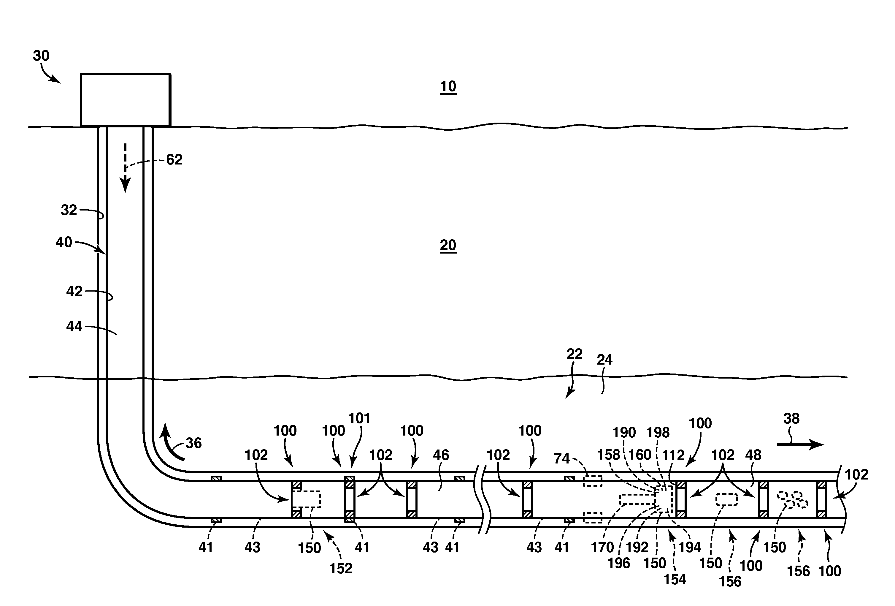
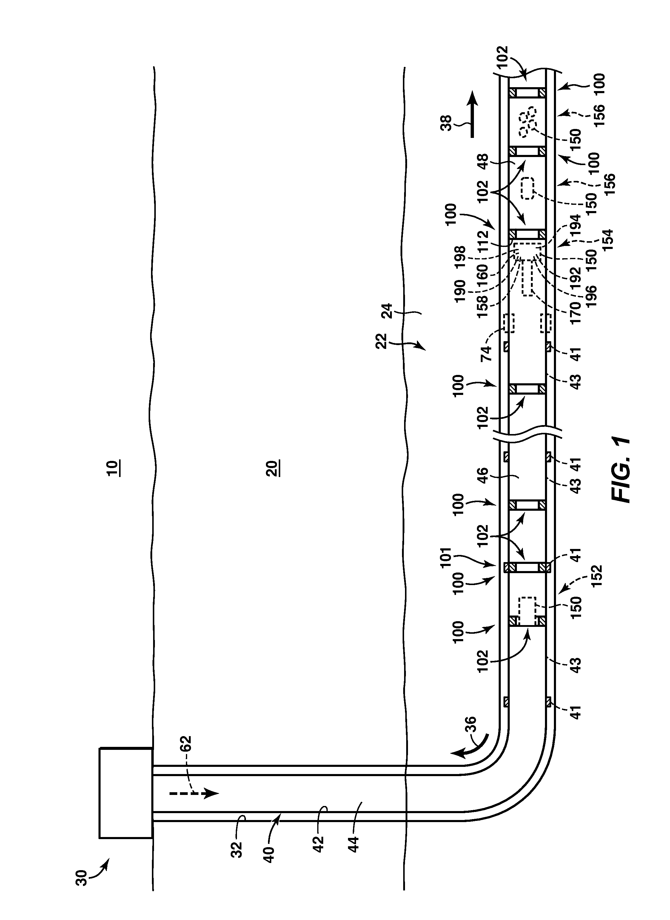
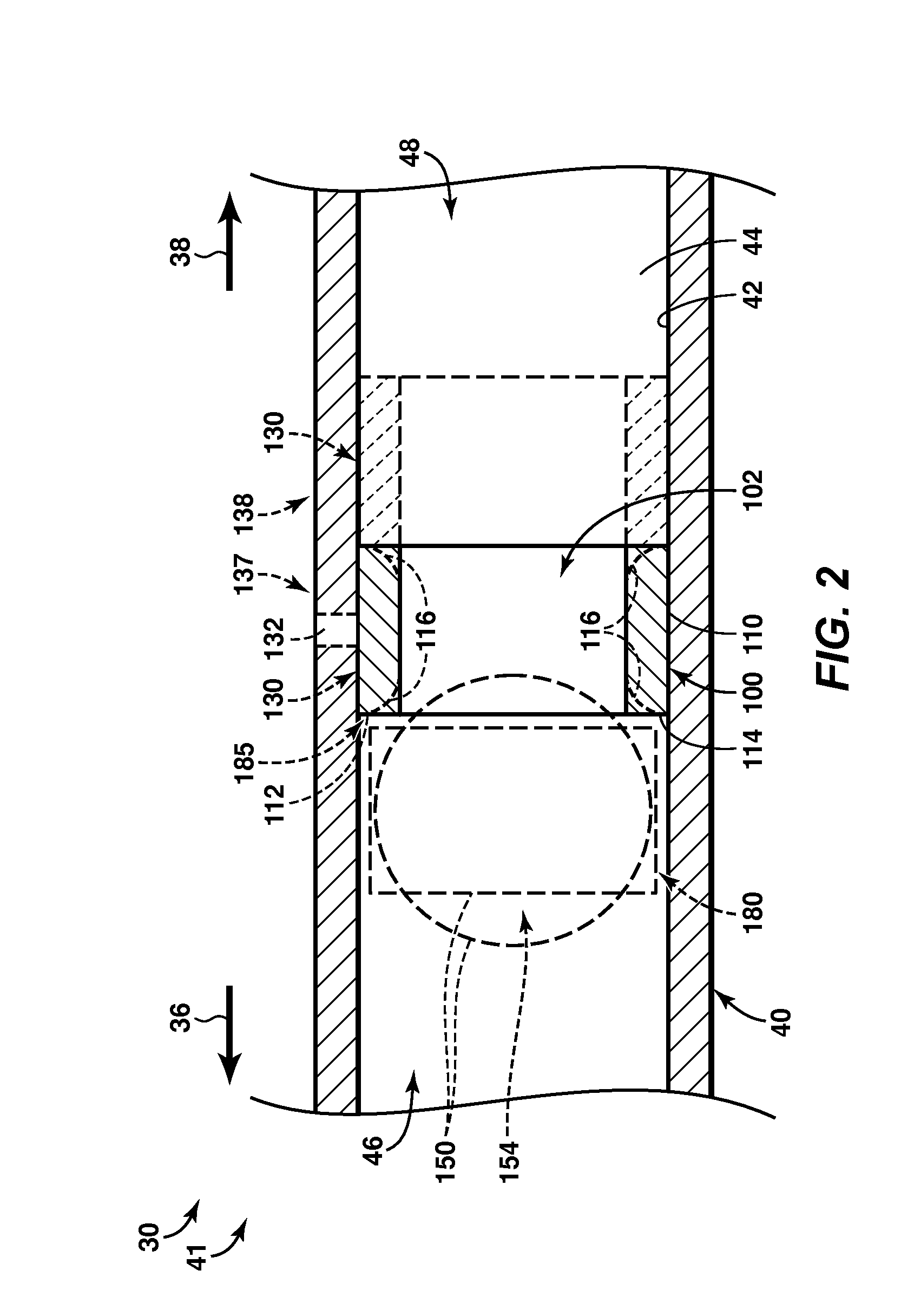
[0028]FIGS. 1-9 provide illustrative, non-exclusive examples of hydrocarbon wells 30 according to the present disclosure and / or of components of hydrocarbon wells 30, such as motion-arresting structures 100 and / or autonomous sealing devices 150. Elements that serve a similar, or at least substantially similar, purpose are labeled with like numbers in each of FIGS. 1-9, and these elements may not be discussed in detail herein with reference to each of FIGS. 1-9. Similarly, all elements may not be labeled in each of FIGS. 1-9, but reference numerals associated therewith may be utilized herein for consistency. Elements, components, and / or features that are discussed herein with reference to one or more of FIGS. 1-9 may be included in and / or utilized with any of FIGS. 1-9 without departing from the scope of the present disclosure.

[0029]In general, elements that are likely to be included in a given (i.e., a particular) embodiment are illustrated in solid lines, while elements that are op...


PUM


Abstract

Systems and methods for restricting fluid flow in a casing conduit, including a wellbore that extends within a subterranean formation, a casing string that extends within the wellbore and defines a portion of the casing conduit, a plurality of motion-arresting structures that project from an inner surface of the casing string to define a plurality of reduced-area regions of the casing conduit, and an autonomous sealing device that defines a contracted configuration and an expanded configuration. The methods include conveying the autonomous sealing device through the casing conduit, determining that the autonomous sealing device is located within a target portion of the casing conduit, expanding the autonomous sealing device to the expanded configuration, retaining the autonomous sealing device on a selected motion-arresting structure, and restricting fluid flow within the casing conduit with the autonomous sealing device.

Description

CROSS REFERENCE TO RELATED APPLICATIONS[0001]This application claims the benefit of U.S. Provisional No. 61 / 871,675, filed Aug. 29, 2013, the entirety of which is incorporated herein by reference for all purposes.FIELD OF THE DISCLOSURE[0002]The present disclosure is directed generally to systems and methods for restricting fluid flow within a casing conduit, and more particularly to systems and methods that utilize an autonomous sealing device and a plurality of motion-arresting structures to restrict fluid flow within the casing conduit.BACKGROUND OF THE DISCLOSURE[0003]A well may be utilized to produce one or more reservoir fluids, such as liquid and / or gaseous hydrocarbons, from a subterranean formation. The well may include a wellbore, which extends between a surface region and the subterranean formation, and a casing string that extends within the wellbore and defines a casing conduit.[0004]During construction and / or operation of the well, it may be desirable to restrict fluid...

Claims


Application Information

Patent Timeline
Patent Type & Authority Applications(United States)
IPC IPC(8): E21B44/00
CPCE21B44/005E21B34/142E21B34/10E21B2200/06E21B43/26
Inventor KUMARAN, KRISHNANTOLMAN, RANDY C.ANGELES BOZA, RENZO M.MORROW, TIMOTHY I.GRUESCHOW, ERIC R.
Owner KUMARAN KRISHNAN
Why Eureka
Try Eureka