Hydraulic damper and a piston for the hydraulic damper assembly

a technology of hydraulic damper and damper assembly, which is applied in the direction of vibration dampers, shock absorbers, liquid based dampers, etc., can solve the problems of affecting the safety, comfort, durability, noise, and difficulty in meeting the requirements of existing passive valve systems, so as to improve the ride comfort and balance of the vehicle, improve the damper characteristics, and reduce the damper harshness

Active Publication Date: 2021-06-03
BEIJINGWEST INDUSTRIES
View PDF0 Cites 2 Cited by
  • Summary
  • Abstract
  • Description
  • Claims
  • Application Information

AI Technical Summary

Benefits of technology

[0008]The present invention in its broadest aspect provides for a hydraulic damper assembly having an improved damper characteristics for low and medium velocity ranges. The present invention also reduces damper harshness, e,g, transition between low speed and medium speeded damping, improves the ride comfort and balance of a vehicle. In addition, the present invention provides a hydraulic damper assembly having improved tunability.
[0009]It is one aspect of the present invention to provide a hydraulic damper assembly. The hydraulic damper assembly comprises a housing extending along a center axis between an opened end and a closed end. The housing defines a fluid chamber extending therebetween for containing a working fluid. A piston is slidably disposed in the fluid chamber dividing the fluid chamber into a compression chamber and a rebound chamber. A piston rod extends along the center axis and couples to the piston for moving the piston between a compression stroke and a rebound stroke. The piston has a compression surface and a rebound surface. The piston defines at least one compression channel, at least one rebound channel, and at least one additional channel, for allowing the working fluid to flow through the piston during the compression stroke and the rebound stroke. The at least one compression channel radially spaced from an exterior surface of the piston and extending from the compression surface to the rebound surface. The at least one rebound channel, radially and circumferentially spaced from the at least one compression channel, extends from the exterior surface toward the compression surface at an oblique angle relative to the center axis. The at least one additional channel, located between the center axis and the at least one compression channel, extends along the piston toward the compression surface. A compression valve is located on the rebound surface of the piston covering the at least one compression channel for limiting working fluid flow through the piston during the compression stroke. A rebound valve is located in the compression chamber and covering the at least one rebound channel for limiting working fluid flow through the piston during the rebound stroke to provide a damping force during the rebound stroke. A proportional bleeding system is located between the compression valve and the piston to establish a bleeding flow passage between the at least one rebound chamber and the additional channel for reducing operation harshness of the hydraulic damper assembly.
[0010]It is another aspect of the present invention to provide a piston for a hydraulic damper assembly. The piston comprises a body extending along a center axis between a compression surface and a rebound surface. The body defines at least one compression channel, at least one rebound channel, and at least one additional channel, for allowing working fluid to flow through the body. The at least one compression channel is radially spaced from an exterior surface of the body and extends from the compression surface to the rebound surface. The at least one rebound channel is radially and circumferentially spaced from the at least one compression channel and extends from the exterior surface toward the compression surface at an oblique angle relative to the center axis. The at least one additional channel is located between the center axis and the at least one compression channel and extends along the body in a parallel relationship with the center axis toward the compression surface. A compression valve is located on the rebound surface of the body covering the at least one compression channel for limiting working fluid flow through the body during the compression stroke. A rebound valve is located in the compression chamber and covering the at least one rebound channel for limiting working fluid flow through the body during the rebound stroke to provide a damping force during the rebound stroke. A proportional bleeding system is located between the compression valve and the body to establish a bleeding flow passage between the at least one rebound chamber and the additional channel for reducing operation harshness of the hydraulic damper assembly.

Problems solved by technology

Although dampers featuring low compression forces with degressive characteristics are required to improve the passengers comfort, during severe road and / or drive conditions they also often lead to maximally admissible wheel-knuckle displacements in damper compression direction leading to a suspension closure or jounce bumper engagement, which in turn affects the car safety, comfort, durability, and noise issues.
It is difficult to fulfill such a requirement for existing passive valve systems because standard valve components have influence as on low as high velocity damper characteristic

Method used


Image

  • Hydraulic damper and a piston for the hydraulic damper assembly
  • Hydraulic damper and a piston for the hydraulic damper assembly
  • Hydraulic damper and a piston for the hydraulic damper assembly

Examples


Embodiment Construction

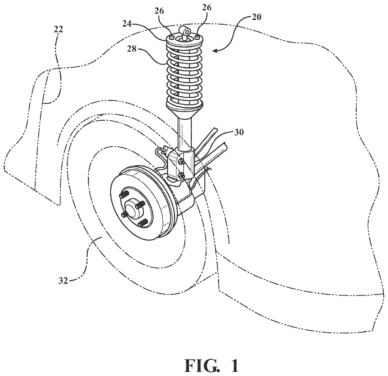
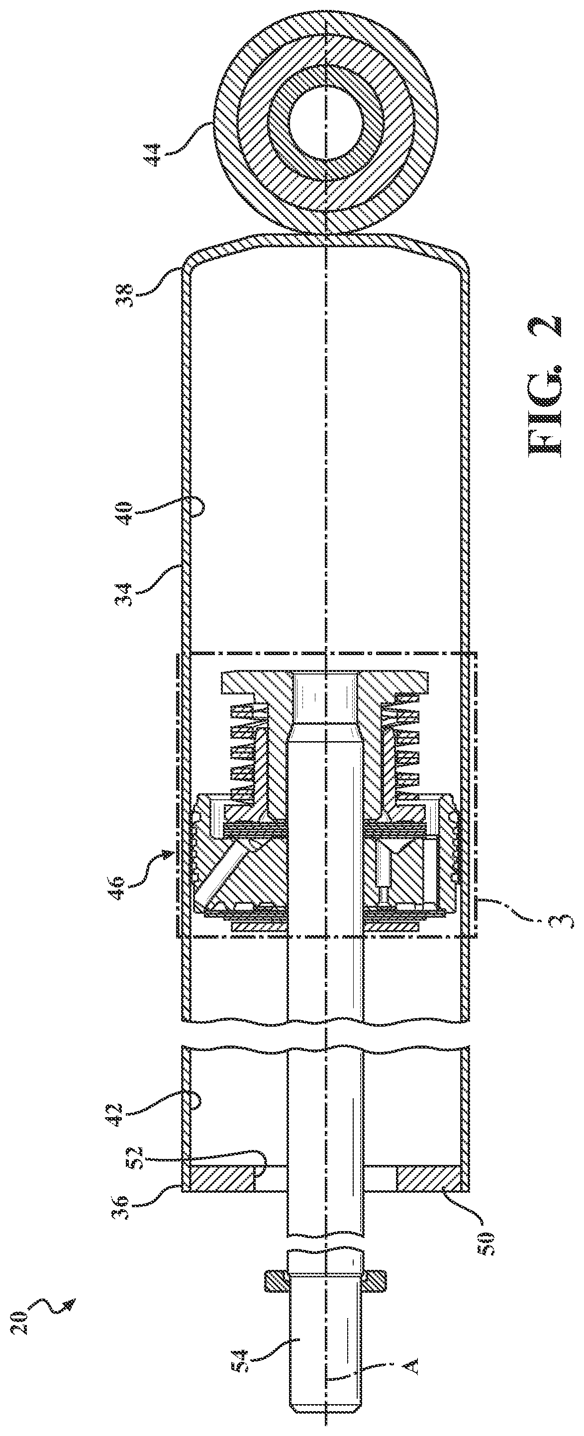
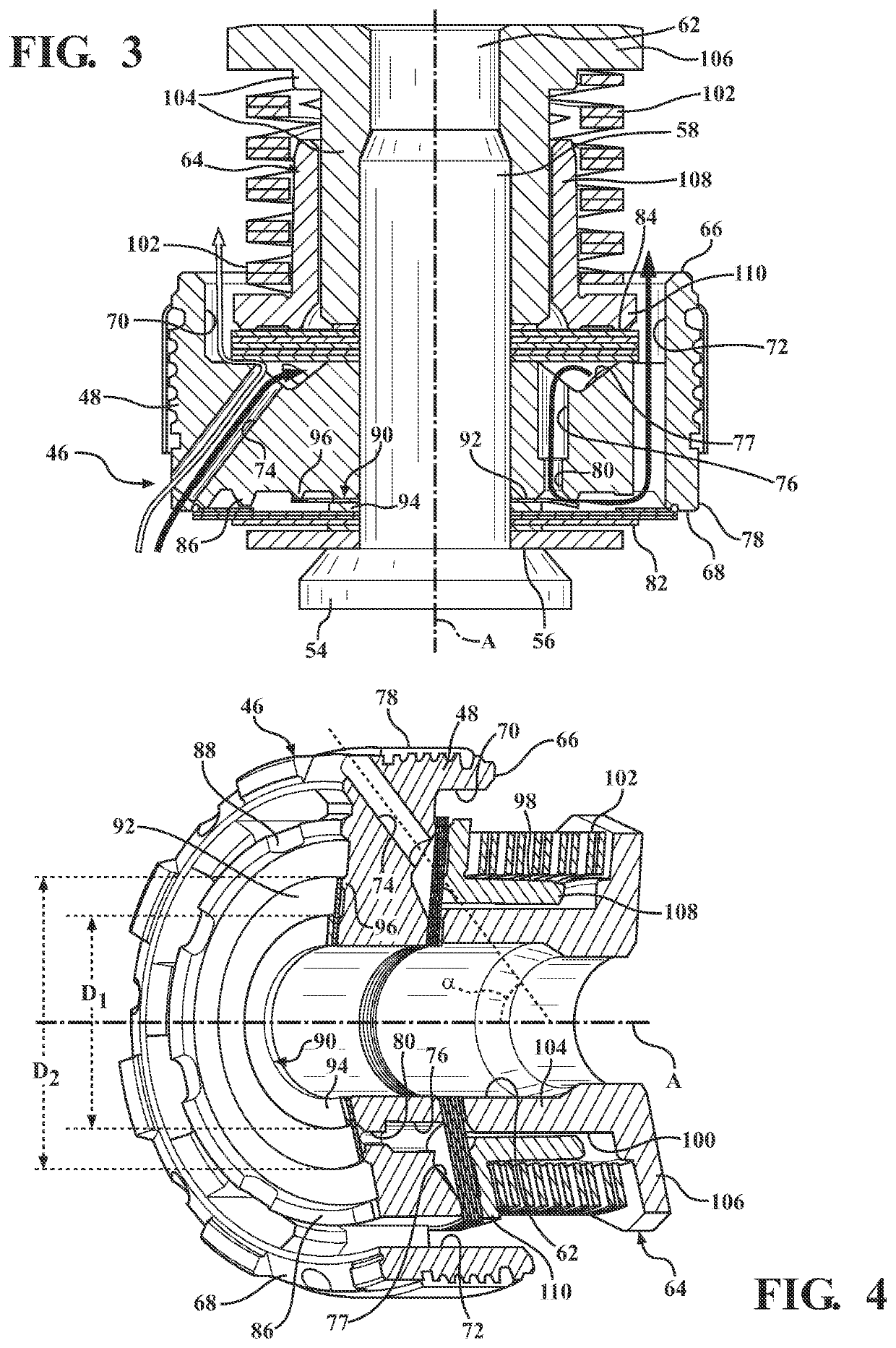
[0018]Referring to the Figures, wherein like numerals indicate corresponding parts throughout the several views, a hydraulic damper assembly 20 constructed in accordance with one embodiment of the present invention is generally shown in FIGS. 1-5.

[0019]FIG. 1 schematically illustrates a fragment of an exemplary vehicle suspension including the hydraulic damper assembly 20 being attached to a vehicle chassis 22 via a top mount 24 and a number of fasteners 26 disposed on a periphery of an upper surface of the top mount 24. The top mount 24 connects to a coil spring 28. The hydraulic damper assembly 20 connects to the steering knuckle 30 supporting a vehicle wheel 32.

[0020]As best shown in FIGS. 2, the hydraulic damper assembly 20 comprises a housing 34, having a generally cylindrical shape, disposed on a center axis A. The housing 34 extends between an opened end 36 and a closed end 38. The housing 34 defines a fluid chamber 40, 42 extending along the center axis A between the opened ...


PUM


Abstract

A hydraulic damper assembly comprises a housing defining a fluid chamber. A piston is slidably disposed in the fluid chamber dividing the fluid chamber into a compression and a rebound chamber. A piston rod couples to the piston for movement between a compression and a rebound stroke. The piston has a compression surface and a rebound surface. The piston defines at least one compression channel, at least one rebound channel, and at least one additional channel. A compression valve covers the at least one compression channel. A rebound valve covers the at least one rebound channel. A proportional bleeding system located between the compression valve and the piston to establish a bleeding flow passage between the at least one rebound chamber and the at least one additional channel for reducing operation harshness of the hydraulic damper assembly. A piston for the hydraulic damper assembly is also disclosed herein.

Description

CROSS-REFERENCE TO RELATED APPLICATION[0001]The present application claims the benefits of U.S. Provisional Application Ser. No. 62 / 942,055, filed on Nov. 29, 2019, and Chinese Patent Application No. 202011116638.3, filed on Oct. 19, 2020, the entire content of which are incorporated herein by reference in their entireties.BACKGROUND OF THE INVENTION1. Field of the Invention[0002]The present invention relates generally to a hydraulic damper assembly and a piston for the hydraulic damper assembly.2. Description of the Prior Art[0003]Hydraulic suspension dampers typically comprise a tube filled with working liquid, inside of which a slidable piston assembly is placed. The piston assembly is attached to a piston rod led outside the damper through the piston rod guide, and comprises a piston with rebound and compression valve assemblies, which control the flow of working liquid passing through the piston assembly during the rebound and the compression stroke of the damper. Some dampers ...

Claims


Application Information

Patent Timeline
Patent Type & Authority Applications(United States)
IPC IPC(8): F16F9/512F16F9/348
CPCF16F9/5126F16F9/3484F16F9/3482F16F9/19F16F9/32F16F9/516F16F9/512F16F9/3214F16F9/3405F16F9/3481
Inventor SLUSARCZYK, PAWELKNAPCZYK, MARCIN
Owner BEIJINGWEST INDUSTRIES
Why Eureka
Try Eureka