Turbine bucket

a turbine bucket and bucket body technology, applied in the direction of liquid fuel engines, vessel construction, marine propulsion, etc., can solve the problems of large sectional area, high centrifugal stress in the dovetail, and insufficient width, so as to reduce the vibration response of the blade portion, increase the exhaust area, and improve the damping characteristic

Active Publication Date: 2008-08-28
MITSUBISHI POWER LTD
View PDF5 Cites 15 Cited by
  • Summary
  • Abstract
  • Description
  • Claims
  • Application Information

AI Technical Summary

Benefits of technology

[0013]The present invention can provide a turbine bucket provided with a shape of the blade root that can make centrifugal stress acting on a blade or dovetail not greater than a limit value of a material even if the blade is increased in length in order to increase an exhaust area and that can ensure a steam passage. Further, the present invention can provide a turbine bucket that can reduce vibration response of a blade portion occurring during operation.
[0014]In particular, the present invention can provide a steel (martensite steel) turbine bucket that can make centrifugal stress acting on a blade or dovetail not greater than a limit value of a material, has such a superior damping characteristic as to reduce vibration response of the blade portion occurring during operation, and has an exhaust area exceeding 9.6 m2 in steam turbine final stage buckets for a rated speed 3600 rpm machine or exceeding 13.8 m2 in steam turbine final state buckets for a rated speed 3000 rpm machine.

Problems solved by technology

Thus, a significantly large sectional area is required.
This case poses the following problems: since the shape of the blade root becomes large, a sufficient width of a steam passage cannot be ensured; and since the weight of the blade becomes too large, high centrifugal stress occurs in the dovetail.
Another of the major problems involved in the increased length of a bucket of a low-pressure turbine final stage is vibration of the turbine bucket.

Method used


Image

  • Turbine bucket
  • Turbine bucket
  • Turbine bucket

Examples


Embodiment Construction

[0047]A description will hereinafter be made of preferred embodiments of the present invention with reference to the drawings.

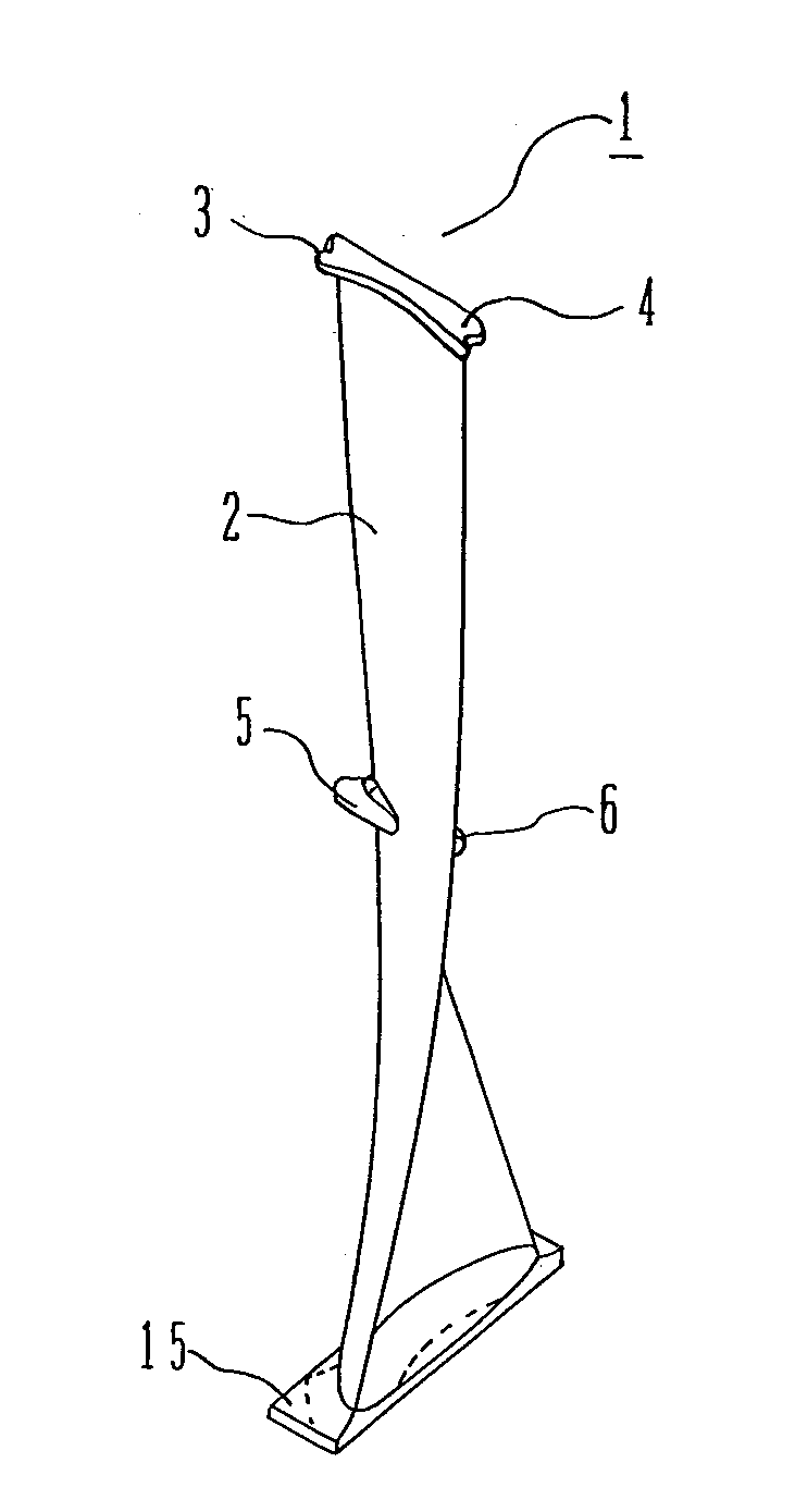
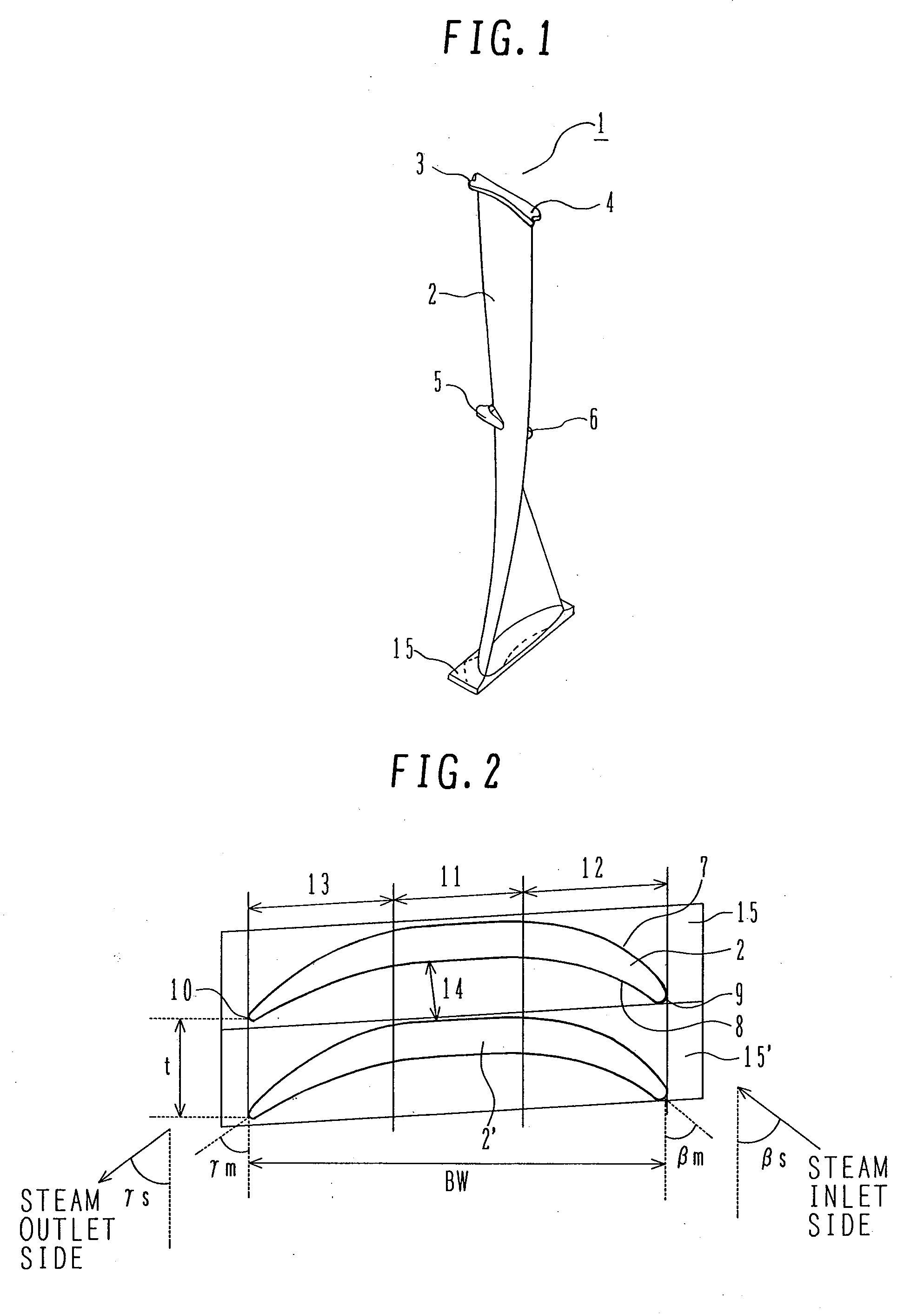
[0048]FIG. 1 is a perspective view illustrating a bucket of a steam turbine according to an embodiment of the present invention. In FIG. 1, there are shown a bucket (blade) or rotor blade 1, a blade portion 2 twisted from a blade root to a blade tip, an integral cover portion (a first connection member on a blade suction side) 3 provided at the blade tip portion so as to extend toward the blade suction side, and an integral cover portion (a first connection member on a blade pressure side) 4 provided at the blade tip portion so as to extend toward the blade pressure side. In addition, there are shown a tie-boss (a second connection member on the blade suction side) 5 projecting on the blade suction side of a blade intermediate portion, a tie-boss (a second connection member on the blade pressure side) 6 projecting on the blade pressure side of the intermediat...


PUM


Abstract

A turbine bucket is provided that can make centrifugal stress acting on a blade or dovetail not greater than a limit value of a material and that is provided with a shape of a blade root that can ensure a steam passage even if the blade is increased in length in order to increase an exhaust area.
The turbine bucket is for a steam turbine low-pressure final stage and has an exhaust area exceeding 9.6 m2 (13.8 m2) in steam-turbine final-stage buckets for a rated speed 3600 rpm (3000 rpm) machine. The turbine bucket is made of martensite steel. A blade portion of the turbine bucket has a suction surface 7 and a pressure surface 8 which are each formed, at a turbine blade root, of three areas consisting of a steam inlet side area 12 with curvature, a steam outlet side area 13 with curvature and an approximately straightly formed area put between the two areas. An airfoil of the turbine bucket root is formed such that the relationship between a blade pitch t and a turbine-axial width BW of the blade portion is BW/t≧5.

Description

BACKGROUND OF THE INVENTION[0001]1. Field of the Invention[0002]The present invention relates to a steam turbine equipped with a turbine bucket applied to a low-pressure turbine final stage and more particularly to a steam turbine used in a thermal electric power plant or the like.[0003]2. Description of the Related Art[0004]In recent years, steam turbines are required to deal with high-power and cost reduction. To meet such requirements, the method is often adopted to increase an area of a turbine bucket through which steam passes (hereinafter called the exhaust area) by increasing the length of the bucket of a low-pressure turbine final stage.[0005]By increasing the exhaust area to increase the amount of steam flowing along the turbine bucket, the power of the steam turbine can be increased and power produced per casing of a low-pressure turbine can be increased. Thus, the number of low-pressure casings of the steam turbine in an output spectrum, which is conventionally two, can b...

Claims


Application Information

Patent Timeline
Patent Type & Authority Applications(United States)
IPC IPC(8): F01D5/14
CPCF01D5/22F01D5/141F01D5/225
Inventor YAMASHITA, YUTAKASENOO, SHIGEKISAITO, EIJIKUDO, TAKESHINAKAMURA, TATEKI
Owner MITSUBISHI POWER LTD
Why Eureka
Try Eureka