
Hydraulic active control vibration absorbing support for railway emergency repair steel truss girder

A technology of active control and steel truss girders, which is applied in bridges, bridge parts, bridge construction, etc., can solve the problems of train running speed, vibration reduction, and impact on vehicle safety and stability that limit the application range of steel truss girders, so as to improve vehicle traffic The effect of speed and safety, reducing the displacement change of the beam structure, and improving the running stability

Active Publication Date: 2019-09-17
SHIJIAZHUANG TIEDAO UNIV
View PDF10 Cites 7 Cited by
  • Summary
  • Abstract
  • Description
  • Claims
  • Application Information

AI Technical Summary

Problems solved by technology

[0002] During the use of the emergency repair steel truss girder as a repair bridge structure, due to its own rigidity limitation, when it is subjected to the load of the train, it will undergo large deformation and vibration, and the vibration interacts with the train, thus limiting the strength of the train. smooth running and driving speed
When the emergency repair steel truss girder is subjected to the dynamic load of the vehicle, the structure will produce a corresponding vibration response, which will affect the use state of the structure and the running stability of the vehicle. The existing emergency repair steel truss girder structure vibration control devices mostly adopt passive or semi-active Control method with limited dampening effect on vibration
[0003] At present, in the design and use of the emergency repair steel truss beam structure, there is no support device that can effectively reduce its vibration response, which limits the scope of application of the steel truss beam and the running speed of the train, and has a great impact on the safe and stable operation of the vehicle.

Method used


Image

  • Hydraulic active control vibration absorbing support for railway emergency repair steel truss girder
  • Hydraulic active control vibration absorbing support for railway emergency repair steel truss girder
  • Hydraulic active control vibration absorbing support for railway emergency repair steel truss girder

Examples


Embodiment Construction

[0034] In order to make the purpose, technical solution and advantages of the present invention clearer, the invention will be clearly and completely described below in conjunction with the accompanying drawings and specific embodiments.

[0035] It is to be understood that the terms "central", "vertical", "transverse", "upper", "lower", "front", "rear", "left", "right", "vertical", "horizontal" ", "top", "bottom", "inner", "outer" and other indicated orientations or positional relationships are based on the orientations or positional relationships shown in the drawings, and are only for the convenience of describing the present invention and simplifying the description, rather than indicating Or imply that the device or element referred to must have a specific orientation, be constructed and operate in a specific orientation, and therefore should not be construed as limiting the invention.

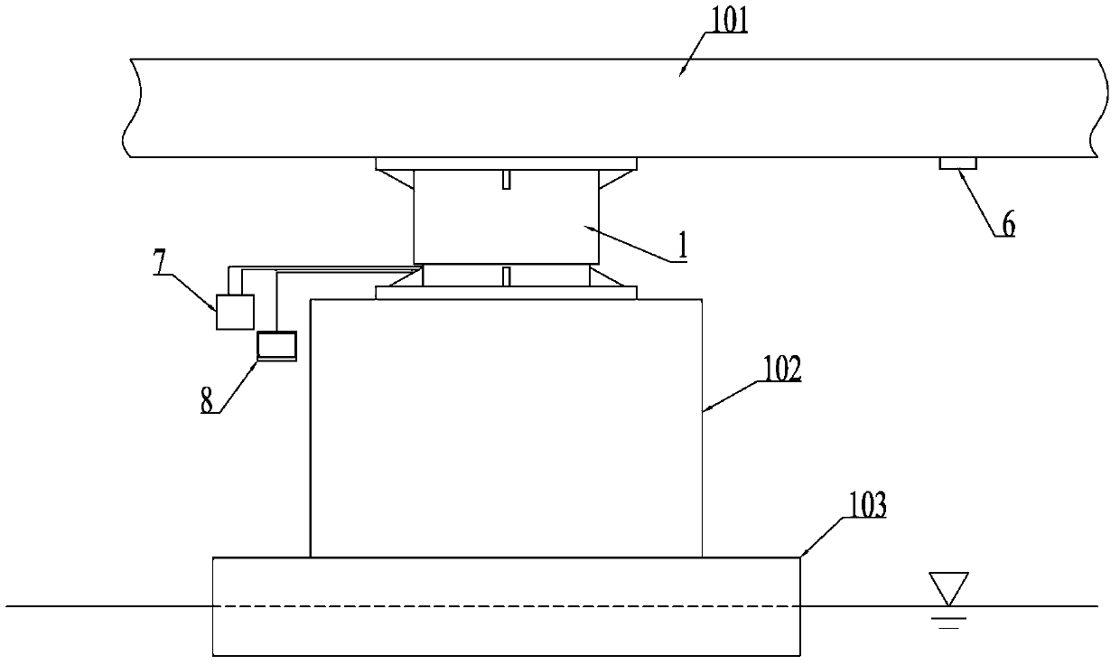
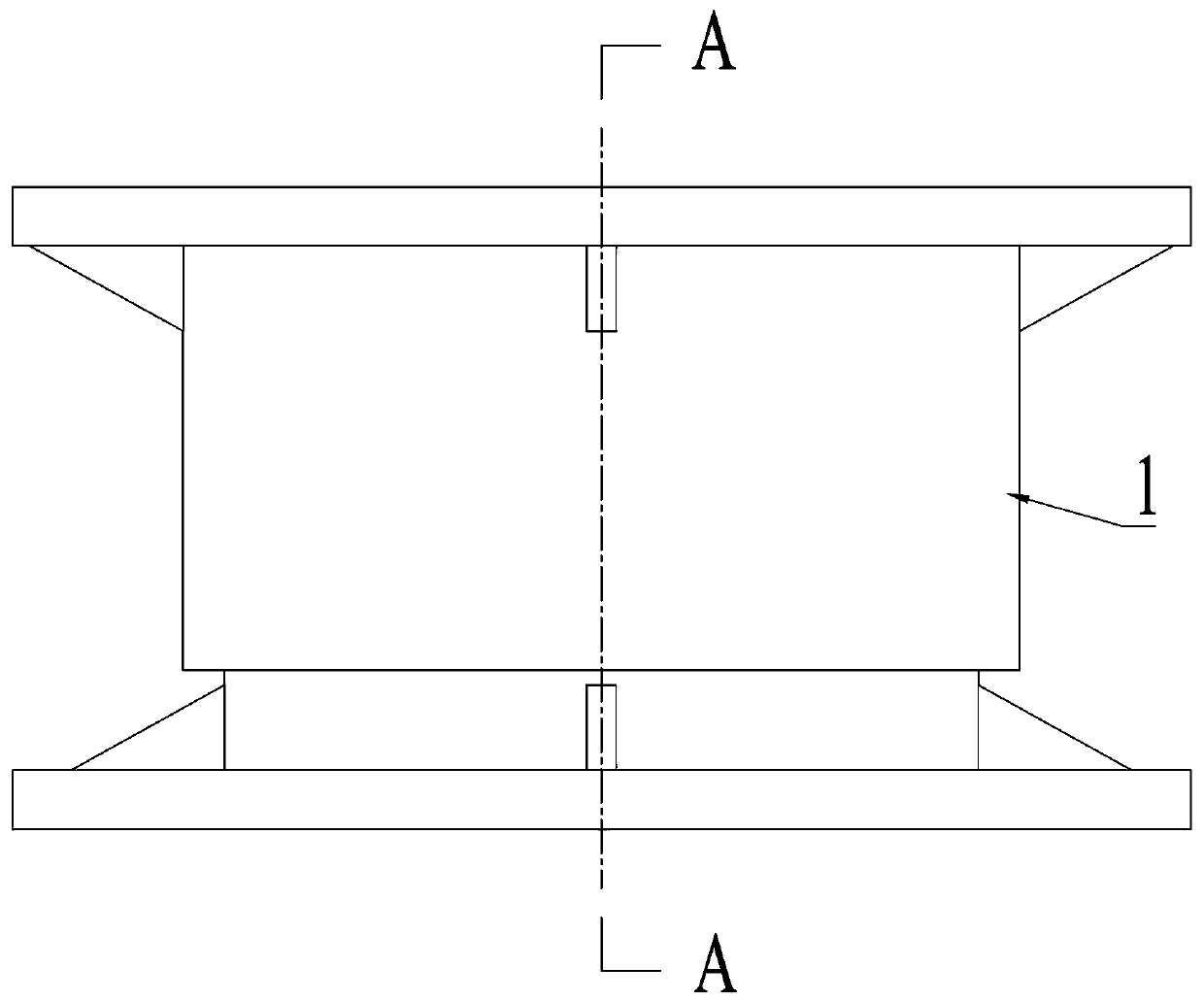
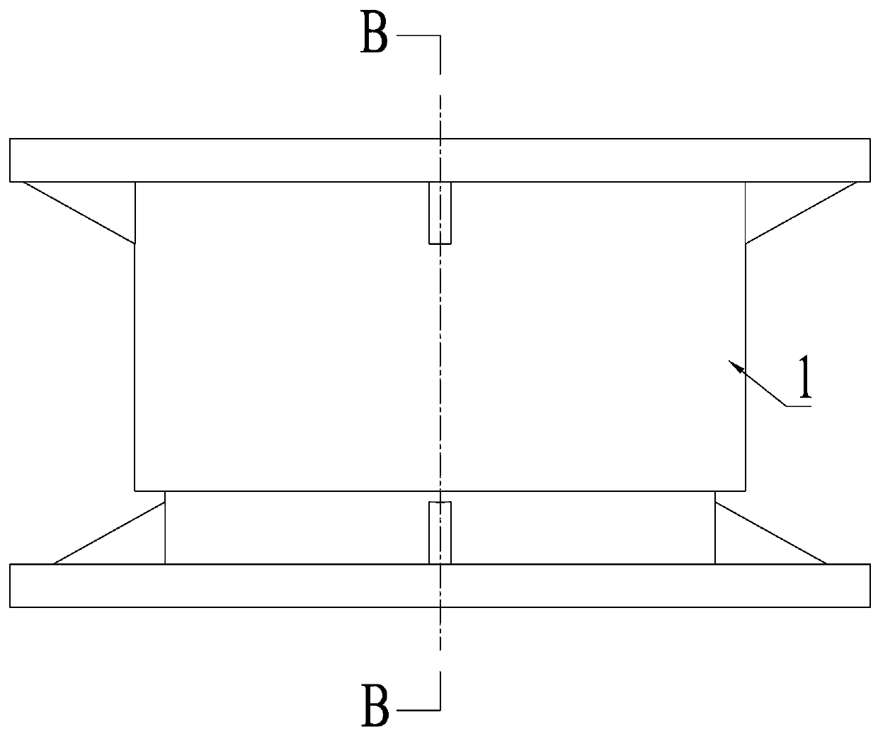
[0036] Such as Figure 1-10 As shown, a hydraulic active control damping support for...


PUM


Abstract

The invention relates to a hydraulic active control vibration absorbing support for a railway emergency repair steel truss girder. The hydraulic active control vibration absorbing support for the railway emergency repair steel truss girder comprises a protective housing, a dynamic hydraulic cylinder, an electro-hydraulic servo valve, a displacement sensor and an acceleration sensor, wherein the dynamic hydraulic cylinder is arranged in the protective housing and comprises a cylinder barrel and a piston; the cylinder barrel is connected with a lower shell; the piston is connected with an upper shell of the protective housing; the electro-hydraulic servo valve is arranged in the protective housing; an oil inlet end and an oil return end of the electro-hydraulic servo valve communicate with a hydraulic source; a control oil end of the electro-hydraulic servo valve communicates with the dynamic hydraulic cylinder; the displacement sensor is fixedly arranged on the cylinder barrel of the dynamic hydraulic cylinder; a top rod of the displacement sensor is fixedly connected with the top of the upper shell of the protective housing; the acceleration sensor is arranged on the upper shell; the displacement sensor and the acceleration sensor are used for detecting vibration data of the steel truss girder and transmitting a detection signal to a controller; a control end of the electro-hydraulic servo valve is connected with the controller; the controller controls the dynamic hydraulic cylinder to act through the electro-hydraulic servo valve; and the dynamic hydraulic cylinder realizes an integral vibration absorbing effect on a bridge structure by using an active exciting mode.

Description

technical field [0001] The invention relates to a bridge damping support, in particular to a hydraulic active control vibration damping support used for railway emergency repair steel truss girders. Background technique [0002] During the use of the emergency repair steel truss girder as a repair bridge structure, due to its own rigidity limitation, when it is subjected to the load of the train, it will undergo large deformation and vibration, and the vibration interacts with the train, thus limiting the strength of the train. smooth running and driving speed. When the emergency repair steel truss girder is subjected to the dynamic load of the vehicle, the structure will produce a corresponding vibration response, which will affect the use state of the structure and the running stability of the vehicle. The existing emergency repair steel truss girder structure vibration control devices mostly adopt passive or semi-active The control method has a limited effect on damping ...

Claims


Application Information

Patent Timeline
Patent Type & Authority Applications(China)
IPC IPC(8): E01D19/04
CPCE01D19/04
Inventor 张淑灏张连朋赵存宝杨泰来冯杰丁淙洋徐光兴沈英明
Owner SHIJIAZHUANG TIEDAO UNIV
Learn More