Turning gradient control valve

A technology of priority valve and one-way valve, applied in the direction of fluid pressure actuation device, servo motor assembly, mechanical equipment, etc., can solve the problems of system vibration, steering hydraulic shock, sudden change of flow, etc., to reduce cavitation noise and flow noise , The oil flow switching is stable, and the effect of ensuring the stability

Inactive Publication Date: 2012-04-11
LANZHOU UNIVERSITY OF TECHNOLOGY
5 Cites 13 Cited by

AI-Extracted Technical Summary

Problems solved by technology

At present, the spool valve port of the hydraulic steering priority valve mostly adopts a non-full-circumference opening with a small opening, that is, a throttle groove structure, and a full-circumference opening form with a large opening. This structure has a sudden change in the area of ​​the valve port, resulting in a sudden change in the flow rate, which is easy Cause steering hydraulic shock, system vibration, noise, system power consumption and other problem...

Abstract

The invention discloses a turning gradient control valve, which is designed to provide a two-functional turning gradient control valve which can absorb vibration of the system, has low noise and energy saving, and can be applied to a static signal type and a dynamic signal type, wherein a first hole (P) in communication with a first throttle groove (4a1) and a second throttle groove (4a2) of a second hole (CF) is arranged on a beading at the right side along the circumference direction; the first hole (P) is in communication with a third throttle groove (4b1) and a fourth throttle groove (4b2) of a third hole (EF), wherein the first throttle groove (4a1) and the second throttle groove (4a2) are matched with a throttle side (5a) of a first sunken cutting groove of a valve body (5a) to form a valve port through which the first hole (P) is led to the second hole (CF); the third throttle groove (4b1) and the fourth throttle groove (4b2) are matched with a throttle side (5b) of a second sunken cutting groove of the valve body (5) to form a valve port through which the first hole (P) is led to the third hole (EF); the left end of the valve core (4) is provided with an asymmetric composite damper (3) while the right end of the valve core (4) is provided with a first damping hole (6).

Application Domain

Technology Topic

Image

  • Turning gradient control valve
  • Turning gradient control valve
  • Turning gradient control valve

Examples

  • Experimental program(1)

Example Embodiment

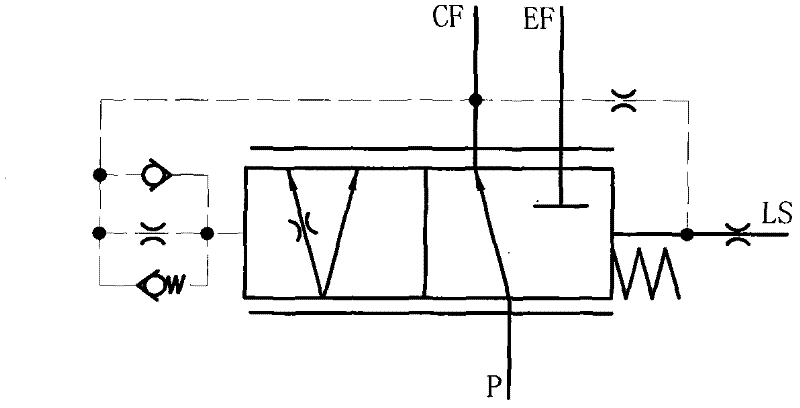
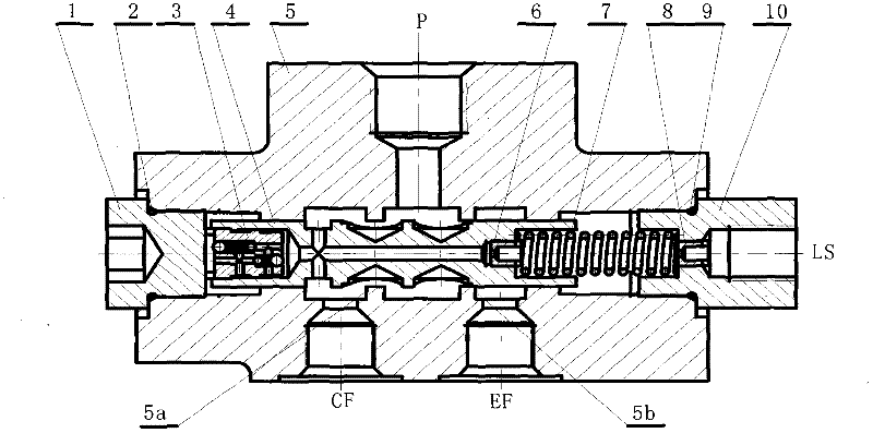
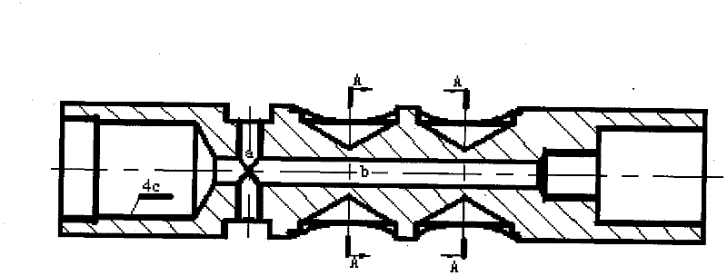
[0009] Such as Figure 1 ~ Figure 2 As shown, the hydraulic steering priority valve is composed of 1. a plug, 2. a sealing ring, 3. a damper, 4. a spool, 5. a valve body, 6. a first orifice, and a spring. Three main undercut grooves are processed on the valve body 5 to communicate with the three main oil through holes, namely the first hole P, the second hole CF, and the third hole EF. The first hole P communicates with the pump oil, and the second Hole CF leads to the steering circuit, and the third hole EF leads to other working circuits. The left end of the valve body 5 is equipped with a plug 1, and the right end is equipped with a spring 7 and a pipe joint 10 with a detachable second orifice 8. The pipe joint 10 and The steering load sensing port LS is connected, and the valve core 4 is installed in the valve body 5. Its initial position is at the leftmost position under the limit of the spring 7 and the plug 1. At this time, the valve port of the first hole P to the second hole CF The opening is the largest, and the valve openings from the first hole P to the third hole EF are zero. The valve core 4 is a double-shoulder hollow structure. A first hole P passes through the second hole CF and the first throttle groove 4a1 and the second throttle groove 4a2 are provided along the circumferential direction on the right shoulder. There are four third throttle grooves 4b1 and four fourth throttle grooves 4b2 of the third hole EF, of which the first throttle groove 4a1, the second throttle groove 4a2 and the first undercut groove throttle edge 5a of the valve body 5 Compose the valve port from the first hole P to the second hole CF, the third throttle groove 4b1, the fourth throttle groove 4b2 and the second undercut groove throttle edge 5b of the valve body 5 form the first hole P to the second hole For the valve port of the three-hole EF, the left end of the spool 4 is equipped with an asymmetric composite damper 3, and the right end is equipped with a first orifice 6.
[0010] Such as Figure 5 As shown, the first hole P passes through the first throttling groove (4a1) of the second hole CF, and the third throttling groove (4b1) of the first hole P passing through the third hole EF is U-shaped groove, and U-shaped groove It is a shallow groove type, that is, the depth of the U-shaped groove is smaller than the width dimension, and the first throttle groove (4a1) is slightly longer than the third throttle groove (4b1); the first hole P passes through the second throttle of the second hole CF The groove (4a2), the fourth throttling groove (4b2) with the first hole P passing through the third hole EF are all drilled on the valve core by a drill, and its shape is characterized by a cylindrical upper part and a conical bottom.
[0011] Such as figure 2 , Figure 7 As shown, the left end of the valve core (4) is equipped with an asymmetric composite damper (3), which is mainly composed of the first one-way valve (3a), the second one-way valve (3b) and the outer cylindrical surface (3c) of the damper and The third orifice (3c-4c) formed by the gap between the inner cylindrical surface (4c) of the valve core; its installation requires the second check valve (3b) and the third orifice when the valve core (4) moves to the left (3c-4c) work, when the valve core (4) moves to the right, the first check valve (3a) and the third orifice (3c-4c) work.
[0012] Figure figure 2 , Picture 9 As shown, when the first orifice (6) is installed at the right end of the spool, the priority valve is a dynamic signal type priority valve, and when the first orifice (6) is replaced with a plug, the priority valve is a static signal type priority valve.
[0013] The working process of the present invention is as follows:
[0014] Such as Figure 1 ~ Figure 2 As shown, under normal conditions, the steering priority valve spool 4 is at the leftmost position under the action of the spring 7, the first port P to the second port CF has the largest opening, and the first port P to the third port EF are closed. ; When working, when the steering priority valve LS port has no steering load signal, the first hole P comes through the first throttle groove 4a1, the second throttle groove 4a2 and the first undercut groove throttle side 5a constitute the valve port The oil flows to the second hole CF, and then the oil flows through the radial hole a on the spool 4 and then divides into two paths. One way passes through the axial hole b on the spool 4 to the left through the first check valve 3a on the damper 3, The third orifice 3c-4c communicates with the left cavity of the spool via oil passages d and c, and the other way flows to the right through the first orifice 6, 8 through the axial hole b on the spool 4 to the LS pipeline. Since the LS port has no steering load pressure, the hydraulic pressure acting on the left end of the spool 4 is greater than the spring force acting on the right end of the spool 4, and the spool moves to the right. At this time, the third throttle groove 4b1 and the fourth throttle groove 4b2 The valve port of the first hole P formed with the second undercutting groove throttling edge 5b leading to the third hole EF is gradually opened. The first orifice 4a1, the second orifice groove 4a2 and the first undercutting groove are throttled The valve port from the first hole P formed by the side 5a to the second hole CF is gradually closed. Under the action of the damper 3, the valve core moves smoothly. When the force at both ends of the valve core is balanced, the valve core is in the rightmost limit position At this time, the opening of the valve port from the first port P to the third port EF is the largest, and the valve port from the first port P to the second port CF is the smallest and only maintains the dynamic signal oil flow to the LS port; when using a plug When replacing the first orifice 6, the dynamic signal oil flow to the LS port is cut off, and the valve is a static signal priority valve at this time.
[0015] When the steering priority valve LS port has a steering load signal, the steering load pressure acting on the right end of the spool 4 plus the spring force is greater than the hydraulic pressure acting on the right end of the spool 4, and the spool moves to the left. At this time, the third throttle The valve port from the first hole P formed by the groove 4b1, the fourth throttle groove 4b2 and the second undercut groove throttling edge 5b to the third hole EF is gradually closed, and the first throttle groove 4a1 and the second throttle The valve port of the first hole P formed by the groove 4a2 and the second undercut groove throttle edge 5b of the valve body 5 to the second hole CF is gradually increased to ensure that the steering hydraulic system has priority over other hydraulic working systems to obtain oil. The leftward movement of the spool moves smoothly under the action of the second one-way valve 3b and the third orifice 3c-4c of the damper 3.

PUM

no PUM

Description & Claims & Application Information

We can also present the details of the Description, Claims and Application information to help users get a comprehensive understanding of the technical details of the patent, such as background art, summary of invention, brief description of drawings, description of embodiments, and other original content. On the other hand, users can also determine the specific scope of protection of the technology through the list of claims; as well as understand the changes in the life cycle of the technology with the presentation of the patent timeline. Login to view more.

Similar technology patents

Classification and recommendation of technical efficacy words

Why Eureka
Try Eureka