
Pump Tube Retention Mechanism

Active Publication Date: 2017-12-14
SPECTRUM MEDICAL
View PDF9 Cites 0 Cited by
  • Summary
  • Abstract
  • Description
  • Claims
  • Application Information

AI Technical Summary

Benefits of technology

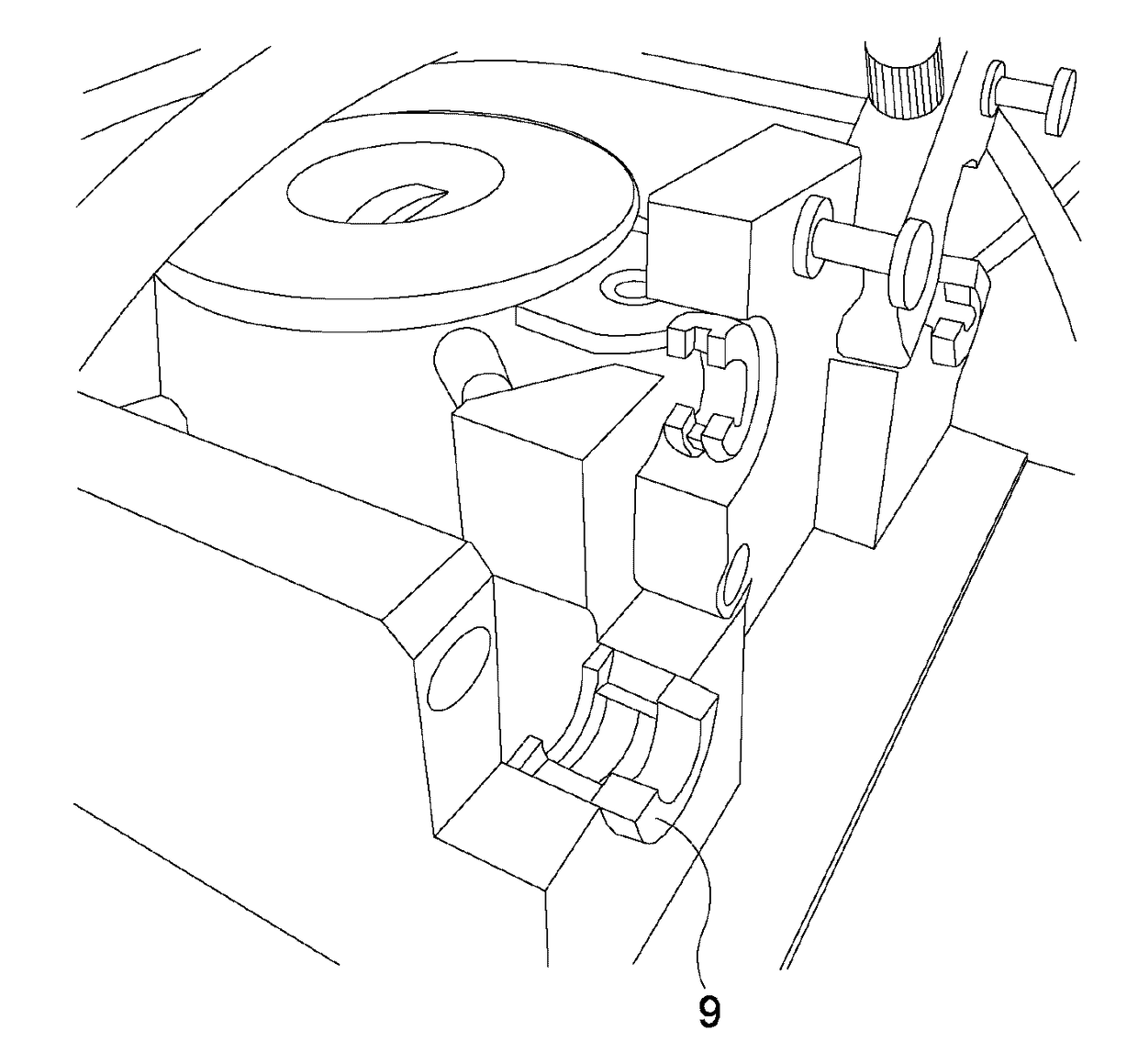
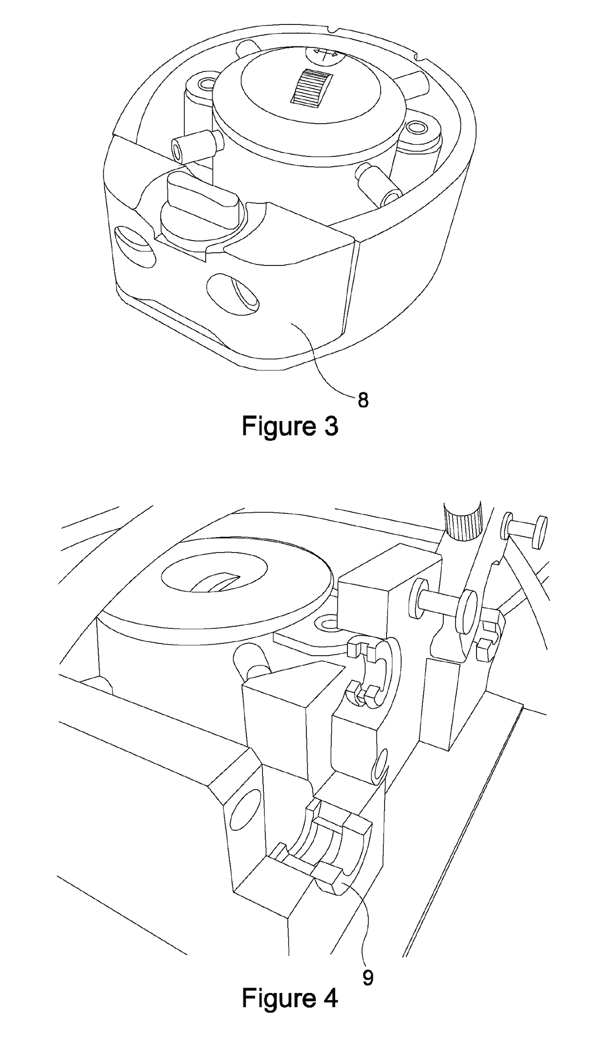
The present invention provides a clamp arrangement for hold a flexible tube during operation of a roller pump for pumping fluid. The clamp arrangement includes a pair of rotatable bobbins with tapered grooves that can grip the tube and prevent it from moving out of the pump housing. The clamp arrangement can securely hold tubes of different shapes and diameters without excessive deformation and restricting fluid flow.

Problems solved by technology

Both of these methods are undesirable for different reasons, one puts a strain on the tube and also restricts the fluid flow within the tube.

Method used


Image

  • Pump Tube Retention Mechanism
  • Pump Tube Retention Mechanism
  • Pump Tube Retention Mechanism

Examples


Embodiment Construction

[0028]With reference to FIG. 5, there is shown a roller pump 10 comprising a housing 12, a rotor 14 and rollers 16. The rotor 14 is located within the housing 12 and a flexible tube 18 is fed around the rotor 14, between the rotor 14 and the housing 12. The rotor 14 is substantially cylindrical and extends longitudinally which, for ease of description, shall be called the vertical direction. The housing 12 has extending vertical walls being substantially parallel to the longitudinal sides of the rotor 14. The tube 18 is located around the housing 12 at approximately the vertical mid-point of the housing 12. Arms 20 connected to the rotor 14 are used to locate the tube 18 in position. The housing 12 comprises a part-circular portion 22 which follows the curvature of the rotor 14 and thus maintains an approximate same distance between the inner walls of the housing 12 and the sides of the rotor 14. This allows the rollers 16 to also maintain an approximate same distance to the inner w...


PUM


Abstract

A clamp arrangement for retaining a flexible tube (18) during operation of a roller pump (10) for pumping fluid, the clamp arrangement comprising a pair of rotatable bobbins (24A, 24B, 26A, 26B) mounted adjacent to each other. Each bobbin (24A, 24B, 26A, 26B) has a tapered groove (30), formed partially around a cylindrical surface of the bobbin (24A, 24B, 26A, 26B), and counter rotation of the bobbins (24A, 24B, 26A, 26B) clamps the tube 18 between the bobbins (24A, 24B, 26A, 26B) in the tapered grooves (30). The clamp arrangement allows tubes of different shapes and diameters to be securely held without overly deforming the tube.

Description

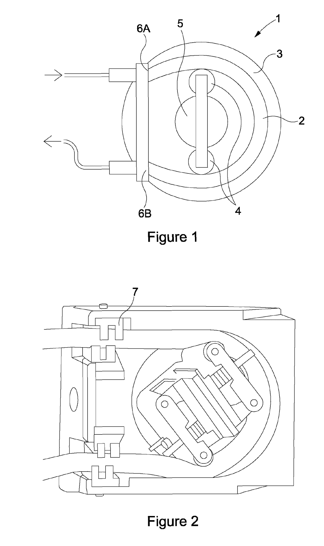
FIELD OF THE INVENTION[0001]The present invention relates to a roller pump tube retention mechanism. Particularly, the present invention relates to an improved system and method for retaining a tube in a roller pump system.BACKGROUND TO THE INVENTION[0002]In many cases it may be desirable when pumping fluid to avoid the fluid coming into contact with pumping components etc. This can avoid cross-contamination and keep the pumped fluid clean and sterile. This is particularly important in cases such as circulating blood for a patient undergoing surgery. A roller, or peristaltic, pump can be used in these circumstances.[0003]FIG. 1 shows an example prior art roller pump 1 used to pump fluid, such as blood. The roller pump 1 utilises a flexible tube 2 in a circular portion of a housing 3 with a number of rotating rollers 4 housed on a rotor 5. These rollers 4 squeeze the fluid along the tube 2 in a continuous motion. The rollers 4 exert a force on the tube 2 which requires it to be firml...

Claims


Application Information

Patent Timeline
IPC IPC(8): A61M39/28F04B43/12F16K35/10F16K7/04
CPCA61M39/287F04B43/12F16K35/10F16K7/04A61M39/285A61M39/286A61M39/28A61M5/142A61M5/14232
Inventor TURNER, STEPHEN
Owner SPECTRUM MEDICAL
Learn More