Paraffin actuated diaphragm valve

a diaphragm valve and paraffin technology, applied in the direction of diaphragm valves, engine diaphragms, instruments, etc., can solve the problems of electromagnetic interference, noise, and difficult operation of solenoid valves, and achieve the effect of improving the cooling time of the volume of paraffin

Active Publication Date: 2020-08-27
HAMILTON SUNDSTRAND CORP
View PDF0 Cites 2 Cited by
  • Summary
  • Abstract
  • Description
  • Claims
  • Application Information

AI Technical Summary

Benefits of technology

[0013]Additionally or alternatively, in this or other embodiments a plurality of heat sink fins are located at the actuator housing to improve cooling time of the volume of paraffin.
[0014]Additionally or alternatively, in this or other embodiments changing the phase of the paraffin from a solid to a liquid urges the actuator rod from a retracted position to an extended position, thereby moving the valve element to restrict the fluid flow through along the flowpath.

Problems solved by technology

Solenoid-operated valves are often large and relatively heavy, and when any dust particles or other contaminants come in contact with the moving parts of the solenoid, the operation of the solenoid valve becomes very difficult, and in such cases the solenoid may not operate as required.
Further, solenoid operated valves typically require a relatively high current to operate the solenoid, and the switching of the solenoid on and off causes electromagnetic interference, or noise, issues.

Method used


Image

  • Paraffin actuated diaphragm valve
  • Paraffin actuated diaphragm valve
  • Paraffin actuated diaphragm valve

Examples


Embodiment Construction

[0030]A detailed description of one or more embodiments of the disclosed apparatus and method are presented herein by way of exemplification and not limitation with reference to the Figures.

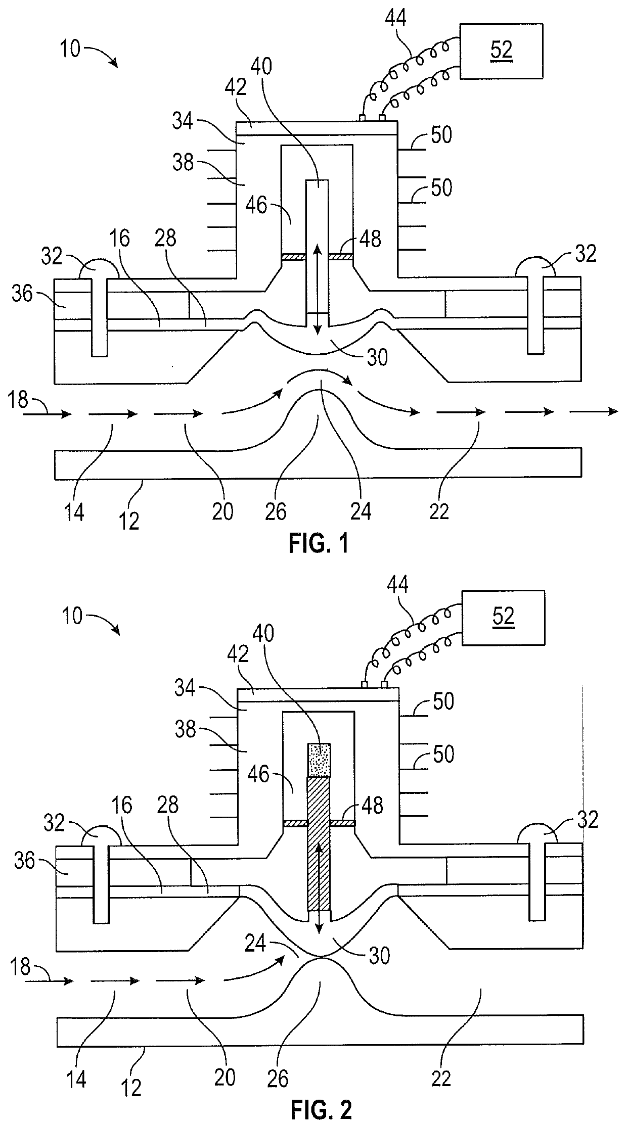
[0031]FIG. 1 is a cross-sectional view of an embodiment of a high output paraffin actuated diaphragm valve 10. The diaphragm valve 10 includes a valve housing 12 defining a fluid flowpath 14 therethrough and a diaphragm 16 located in the valve housing 12 that is movable into and / or out of the fluid flowpath 14 to control a fluid flow 18, which may be, for example, a liquid, gas, or two-phase fluid, along the fluid flowpath 14. In some embodiments, the fluid flowpath 14 includes an upstream flowpath portion 20 and a downstream flowpath portion 22, separated by a flowpath throat 24. In some embodiments, the flowpath throat 24 is defined in part by a protrusion 26 of the valve housing 12 into the fluid flowpath 14.

[0032]The diaphragm 16 includes a fixed diaphragm portion 28 and a movable diaphragm p...


PUM


Abstract

A valve includes a valve housing defining a fluid flowpath therethrough, a valve element located in the valve housing and movable in the fluid flowpath to regulate a fluid flow therethrough, and a valve actuator operably connected to the valve element to urge movement of the valve element in the fluid flowpath. The valve actuator includes an actuator housing, a volume of paraffin located in the housing, and an actuator rod located in the actuator housing and operably connected to the valve element, such that phase change of the paraffin urges movement of the actuator rod between a first position and a second position, thereby moving the valve element between a retracted position and an extended position.

Description

CROSS-REFERENCE TO RELATED APPLICATIONS[0001]This application claims the benefit of Indian Application No. 201911007680 filed Feb. 27, 2019, which is incorporated herein by reference in its entirety.BACKGROUND[0002]Exemplary embodiments pertain to the art of valves and valve control.[0003]In typical valves, liquid or gas flow control through the valve is accomplished utilizing one or more solenoids, or by utilizing manual operation to open and / or close the valve thereby regulating the flow of liquid or gas therethrough. The solenoid control system requires an electronic circuit, which provides pull in current and hold in current. Solenoid-operated valves are often large and relatively heavy, and when any dust particles or other contaminants come in contact with the moving parts of the solenoid, the operation of the solenoid valve becomes very difficult, and in such cases the solenoid may not operate as required. Further, solenoid operated valves typically require a relatively high c...

Claims


Application Information

Patent Timeline
Patent Type & Authority Applications(United States)
IPC IPC(8): F16K31/00F16K7/12
CPCF01N2240/36F02D9/06F16K31/047F16K31/002F02D9/1065G05D23/1921F16K7/126F16K31/025
Inventor SRINIVASA, VINAY KUMAR
Owner HAMILTON SUNDSTRAND CORP
Why Eureka
Try Eureka