Scanning galvanometer laser-high frequency pulse TIG composite welding method

A high-frequency pulse and scanning galvanometer technology, which is applied in laser welding equipment, welding equipment, welding accessories, etc., can solve problems such as poor fusion of side walls and interlayers, poor formation of bottom welding, and large welding heat input, etc., to achieve Improve the quality of interlayer fusion, avoid the collapse of molten pool, and reduce the effect of heat input

Pending Publication Date: 2020-02-21
中国船舶集团渤海造船有限公司
View PDF9 Cites 9 Cited by
  • Summary
  • Abstract
  • Description
  • Claims
  • Application Information

AI Technical Summary

Problems solved by technology

[0005] In order to overcome the problems of large welding heat input, low welding efficiency, poor bottom welding formation, and poor fusion between side walls and layers in the prior art, the present invention proposes a scanning galvanometer laser-high frequency pulse TIG composite welding method
Solve the technical problems of laser arc hybrid welding

Method used


Image

  • Scanning galvanometer laser-high frequency pulse TIG composite welding method
  • Scanning galvanometer laser-high frequency pulse TIG composite welding method
  • Scanning galvanometer laser-high frequency pulse TIG composite welding method

Examples


Embodiment 1

[0018] Taking the SA-738 Gr.B steel butt horizontal welding with a plate thickness of 50mm and a blunt edge of 6mm as an example, the welding implementation steps and process are explained in detail.

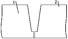
[0019] Groove making: machine the workpiece 1 to be welded and the workpiece 2 to be welded to make a welding groove;

[0020] Assembly: Assemble the workpiece to be welded and the workpiece to be welded;

[0021] Removal of dirt: remove scale, oil, rust, water and other dirt from the groove and its surroundings before welding;

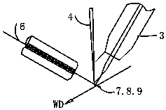
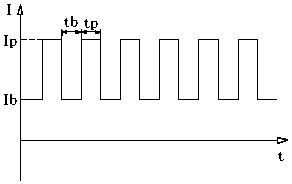
[0022] Bottom welding: scanning galvanometer laser-high-frequency pulse TIG composite welding torch 3 is used for bottom welding through laser beam 4, welding wire 6 has a diameter of φ1.2mm, laser power is 3.5kW, and the scanning shape is linear 7, and the scanning width is 2mm. Speed ​​250mm / s, peak current 350A, base current 105A, duty cycle 50%, pulse frequency 300HZ, welding speed 300mm / min, argon flow 20L / min;

[0023] Filling welding: scanning ...

Embodiment 2

[0025] Taking the horizontal butt welding of A514 Gr.Q steel with a plate thickness of 60mm and a blunt edge of 8mm as an example, the welding implementation steps and process are explained in detail.

[0026] Groove making: machine the workpiece to be welded and the workpiece to be welded to make a welding groove;

[0027] Assembly: Assemble the workpiece to be welded and the workpiece to be welded;

[0028] Removal of dirt: remove scale, oil, rust, water and other dirt from the groove and its surroundings before welding;

[0029] Bottom welding: scanning galvanometer laser-high frequency pulse TIG composite welding torch is used for bottom welding with laser beam, welding wire diameter φ1.0mm, laser power 4.5kW, scanning shape is circular 8, scanning width 1.5mm, swing speed 500mm / s, peak current 400A, base current 160A of peak current, duty cycle 50%, pulse frequency 500HZ, welding speed 350mm / min, argon gas flow rate 15L / min;

[0030] Filling welding: scanning galvanome...


PUM


Abstract

The invention provides a scanning galvanometer laser-high frequency pulse TIG composite welding method. A steel plate to be welded is made into a welding groove, and assembling and cleaning are carried out. A first workpiece to be welded is in butt joint with a second workpiece to be welded. The first workpiece to be welded and the second workpiece to be welded are thick steel plates. A welding seam to be welded with the selected width and length is formed between the two workpieces to be welded. A welding wire is used, laser beams generated by a scanning galvanometer laser-high frequency pulse TIG composite welding gun and a TIG welding gun are used for travelling welding for the welding seam in the direction from one end to the other end, and a mode of a straight-line swing, a circular swing or a "8-shaped" swing is adopted in the welding process. According to the scanning galvanometer laser-high frequency pulse TIG composite welding method, scanning galvanometer laser-high frequencypulse TIG composite welding is adopted, the probability of pore generation can be reduced, the welding seam property is improved, the welding seam heat input is reduced, and the welding deformation is reduced. The scanning galvanometer laser-high frequency pulse TIG composite welding method is suitable to be used as a method of swing laser-high frequency pulse TIG composite welding for members ofthick wall high-strength steel, stainless steel and the like.

Description

technical field [0001] The invention relates to the technical field of laser welding, in particular to a scanning galvanometer laser-high frequency pulse TIG composite welding method. Background technique [0002] Components such as thick-walled high-strength steel and stainless steel are widely used in important national industrial fields such as marine and nuclear power. At present, traditional arc welding methods such as TIG, MAG or SMAW are usually used for welding. The welding speed is slow, the welding efficiency is low, and the welding quality is not high. [0003] Laser welding has the advantages of high energy density, fast welding speed, good weld quality, large aspect ratio, small heat-affected zone, and small welding deformation. It has been widely used in industrial production. However, due to the small diameter of single laser welding spot , The assembly accuracy of the weld seam is high, the back of the bottom welding is poorly formed, and the weld seam cools ...

Claims


Application Information

Patent Timeline
Patent Type & Authority Applications(China)
IPC IPC(8): B23K28/02B23K26/21B23K26/082B23K9/167B23K9/09B23K9/32
CPCB23K28/02B23K26/21B23K26/082B23K9/167B23K9/09B23K9/32
Inventor 刘殿宝吴满鹏李洋赵俊凯齐伟陈治坤高扬刘丽华陈嵩
Owner 中国船舶集团渤海造船有限公司
Why Eureka
Try Eureka