
Portable eye tracking device

a technology of eye tracking and portable devices, which is applied in the field of eye tracking or gaze detection technology, can solve the problems of degrading affecting the performance of existing portable eye tracking systems, and affecting the accuracy of readings,

Active Publication Date: 2015-03-05
TOBII TECH AB
View PDF8 Cites 66 Cited by
  • Summary
  • Abstract
  • Description
  • Claims
  • Application Information

AI Technical Summary

Benefits of technology

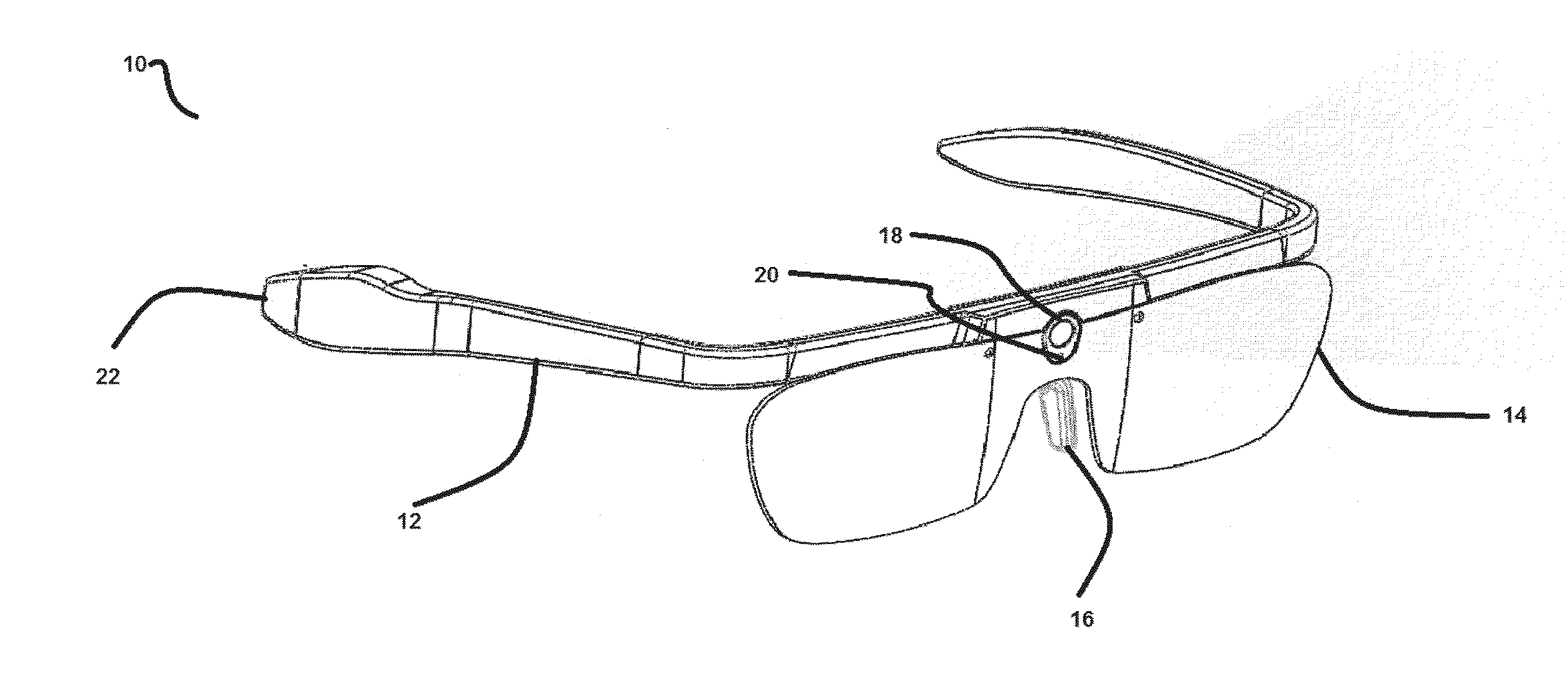
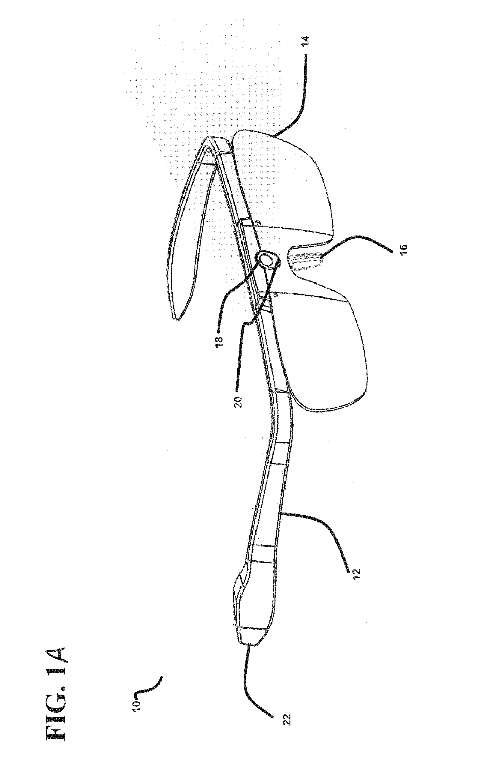
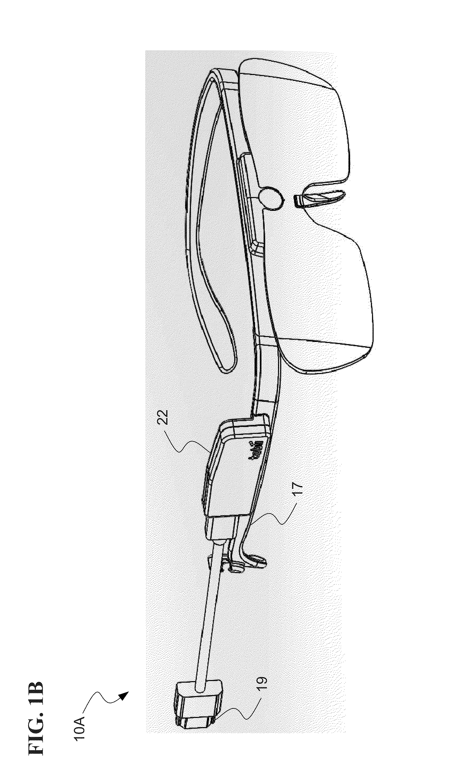
The patent describes a portable eye tracker device that can be worn by a user and has a frame with an illuminator and an image sensor. The device also has a movement sensor that detects any movement of the frame. The device can capture images of the user's eyes and track the user's gaze direction based on the image data and information from the movement sensor. This technology can be used in various applications such as eye-controlled gaming or sports equipment.

Problems solved by technology

Existing portable eye tracking systems may suffer severe performance degradation when the equipment moves relative to the wearer's head.
For designs requiring calibration, such movement of the glasses relative to the wearer's head may negate the calibration and significantly degrade the accuracy of the readings.
As another example, a single-camera portable eye tracking system may render substantially degraded reading in certain conditions including when the wearer is in the presence of strong light sources; is exposed to direct sunlight; or when the single camera's view is obstructed such as by an eyelash.
Furthermore, such single-camera systems may be unable to detect gaze directions at the extremities of a user's field of view.

Method used


Image

  • Portable eye tracking device
  • Portable eye tracking device
  • Portable eye tracking device

Examples


Embodiment Construction

[0020]The ensuing description provides exemplary embodiments only, and is not intended to limit the scope, applicability or configuration of the disclosure. Rather, the ensuing description of the exemplary embodiments will provide those skilled in the art with an enabling description for implementing one or more exemplary embodiments. It shall be understood that various changes may be made in the function and arrangement of elements without departing from the spirit and scope of the invention as set forth in the appended claims. For example, any detail of one embodiment discussed herein may or may not be present in all possible variations of that embodiment, and may or may not be present in all possible variations of other embodiments discussed herein.

[0021]Specific details are given in the following description to provide a thorough understanding of the embodiments. However, it will be understood by one of ordinary skill in the art that the embodiments may be practiced without thes...


PUM


Abstract

A portable eye tracker device is disclosed which includes a frame, at least one optics holding member, a movement sensor, and a control unit. The frame may be a frame adapted for wearing by a user. The at least one optics holding member may include at least one illuminator configured to selectively illuminate at least a portion of at least one eye of the user, and at least one image sensor configured to capture image data representing images of at least a portion of at least one eye of the user. The movement sensor may be configured to detect movement of the frame. The control unit may be configured to control the at least one illuminator for the selective illumination of at least a portion of at least one eye of the user, receive the image data from the image sensors, and receive information from the movement sensor.

Description

CROSS-REFERENCE TO RELATED APPLICATIONS[0001]This application claims priority to Provisional U.S. Patent Application No. 61 / 873,154 filed Sep. 3, 2013, entitled “PORTABLE EYE TRACKING DEVICE,” the entire disclosure of which is hereby incorporated by reference, for all purposes, as if fully set forth herein.[0002]This application is also related to U.S. patent application Ser. No. ______ filed concurrently herewith, entitled “PORTABLE EYE TRACKING DEVICE,” (Attorney Docket No. 89056-908793), U.S. patent application Ser. No. ______ filed concurrently herewith, entitled “PORTABLE EYE TRACKING DEVICE,” (Attorney Docket No. 89056-909170), and U.S. patent application Ser. No. ______ filed concurrently herewith, entitled “PORTABLE EYE TRACKING DEVICE,” (Attorney Docket No. 89056-909171), the entire disclosures of which are hereby incorporated by reference, for all purposes, as if fully set forth herein.BACKGROUND OF THE INVENTION[0003]Methods for determining a point at which a user is look...

Claims


Application Information

Patent Timeline
Patent Type & Authority Applications(United States)
IPC IPC(8): G06F3/01H04N5/225
CPCG06F3/013H04N5/2256H04N5/2254A61B3/113G02B2027/0138G02B2027/0187G06T7/74G02B27/017G02B2027/0178H04R1/32G06T2207/30201G06T2207/10152H04R2201/40G02B2027/014H04N23/55H04N23/56
Inventor GUSTAFSSON, SIMONANDERSSON, JONASENGWALL, ERIKHAINZL, RICHARDLEKSEN, LARS-OLACEDERLUND, MARKUS
Owner TOBII TECH AB
Learn More