Vision enhancing device

Inactive Publication Date: 2015-03-05
OPTELEC DEV BV
View PDF3 Cites 5 Cited by
  • Summary
  • Abstract
  • Description
  • Claims
  • Application Information

AI Technical Summary

Benefits of technology

[0023]Preferably said second mechanical brake comprises a rigid longitudinal brake rod attached to the table and extending in the second direction, and a brake shoe, which brake shoe is—under user control—arranged for being positioned from an idle position to an active position, in which active position the brake shoe engages the longitudinal brake rod and in which idle position the brake shoe is free from the longitudinal rod. Such a second mechanical brake can function effectively and reproducibly over an extended period of time. A particularly mechanical robust and compact vision enhancing device can be realized when the second mechanical brake comprises a brake shoe formed by two translatable rotatable brake shoe portions positioned at either side of the longitudinal brake rod, said rotatable brake shoe portions being translatable relative to each other by a second worm wheel mounted on the intermediate mid-table, said second worm wheel being rotatable by means of a second control rod, wherein the second control rod is slidable along a longitudinal direction of the second control rod within the second worm wheel. Preferably a free end of the second control rod is provided with a second gear wheel that is in engagement with a second rack that is slidably attached to the table in a direction parallel to the first direction. Preferably the vision enhancing device is provided with an eccentric that is engaged by the second worm wheel on the one hand for rotation of the eccentric upon rotation of the second worm wheel and which eccentric engages the brake shoe portions such that if the eccentric is ro

Problems solved by technology

This positioning behind the screen requires a large depth of the vision enhancing device for displacing the table, especially when using large objects, having a len

Method used


Image

  • Vision enhancing device
  • Vision enhancing device
  • Vision enhancing device

Examples


Embodiment Construction

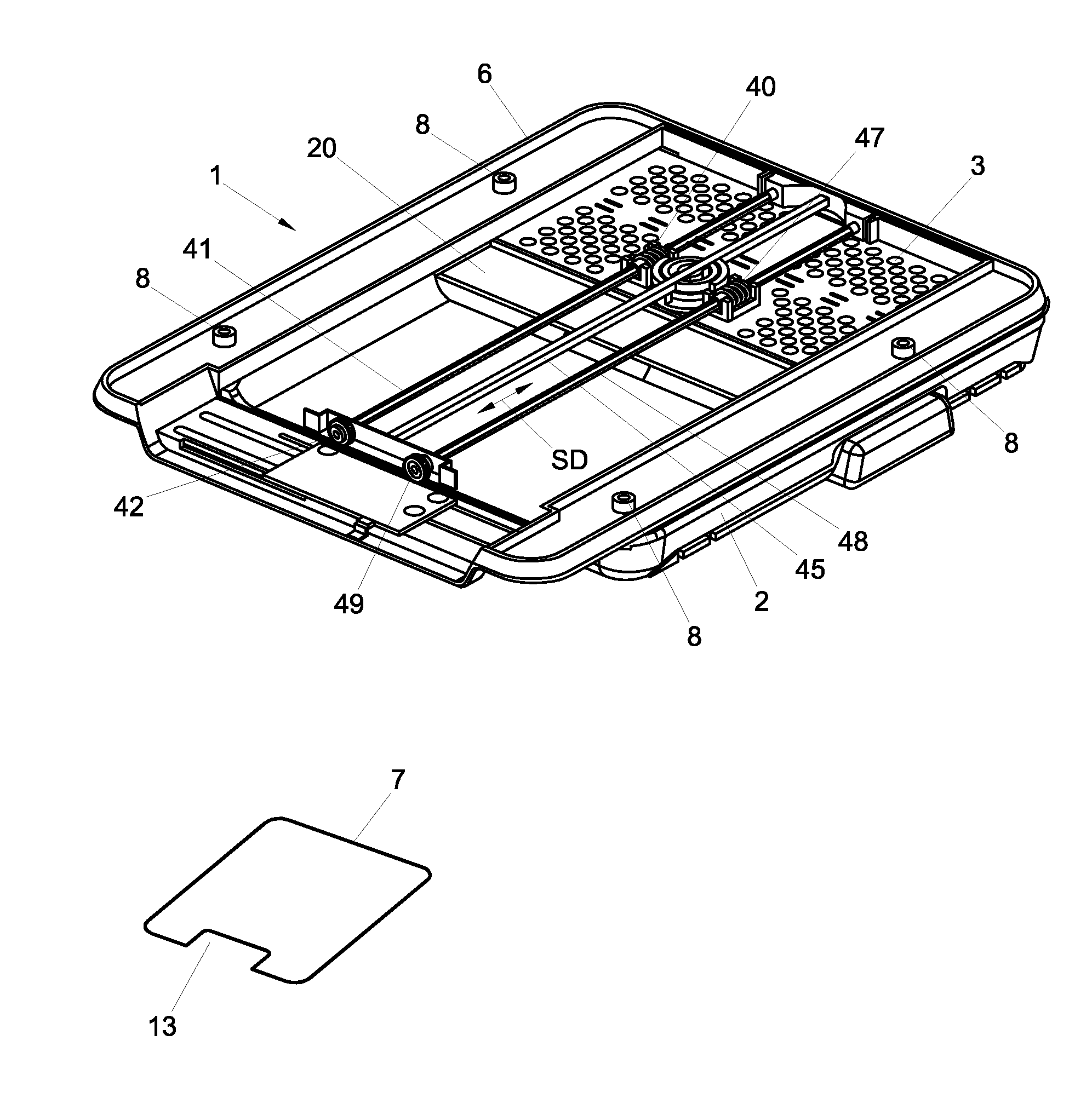
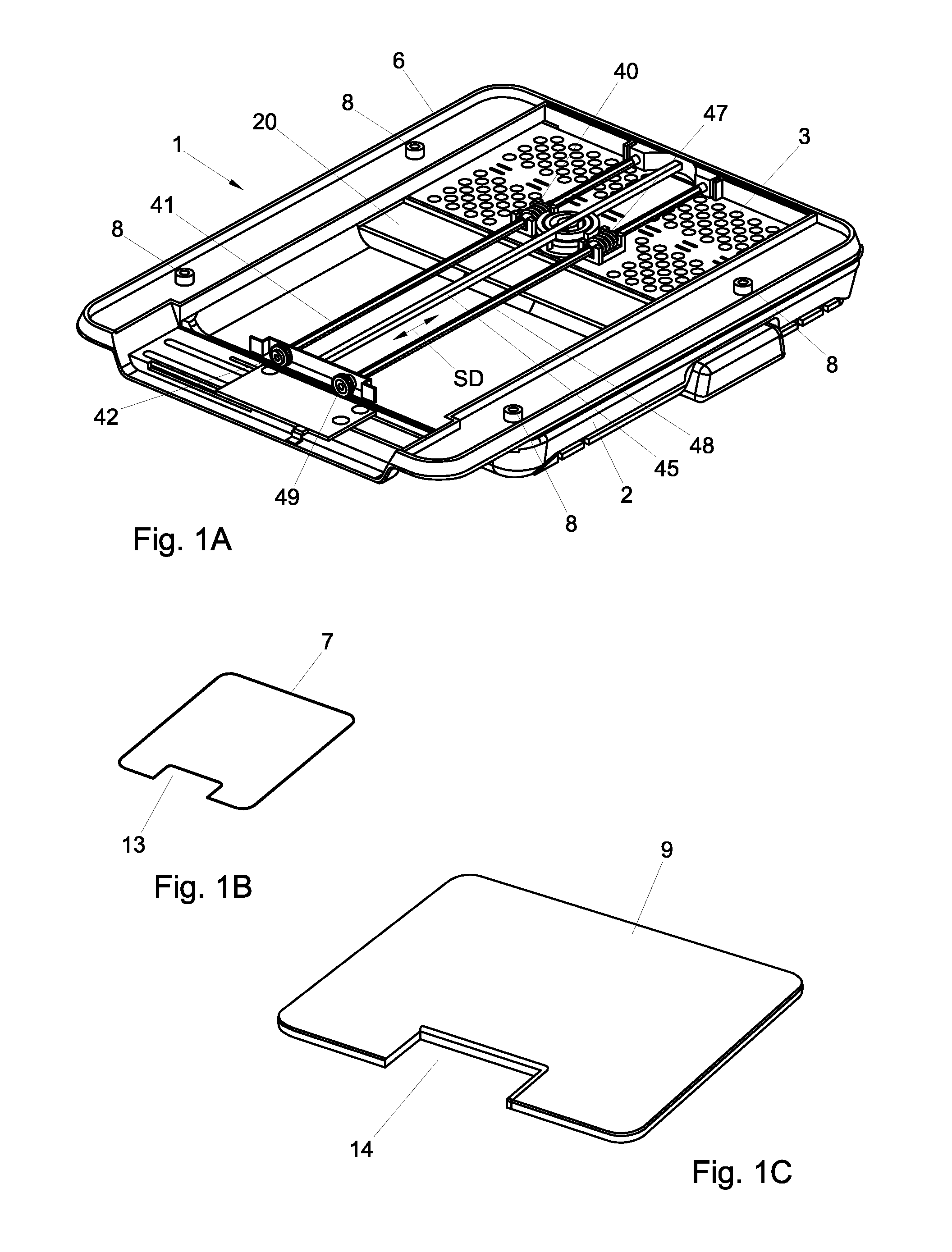
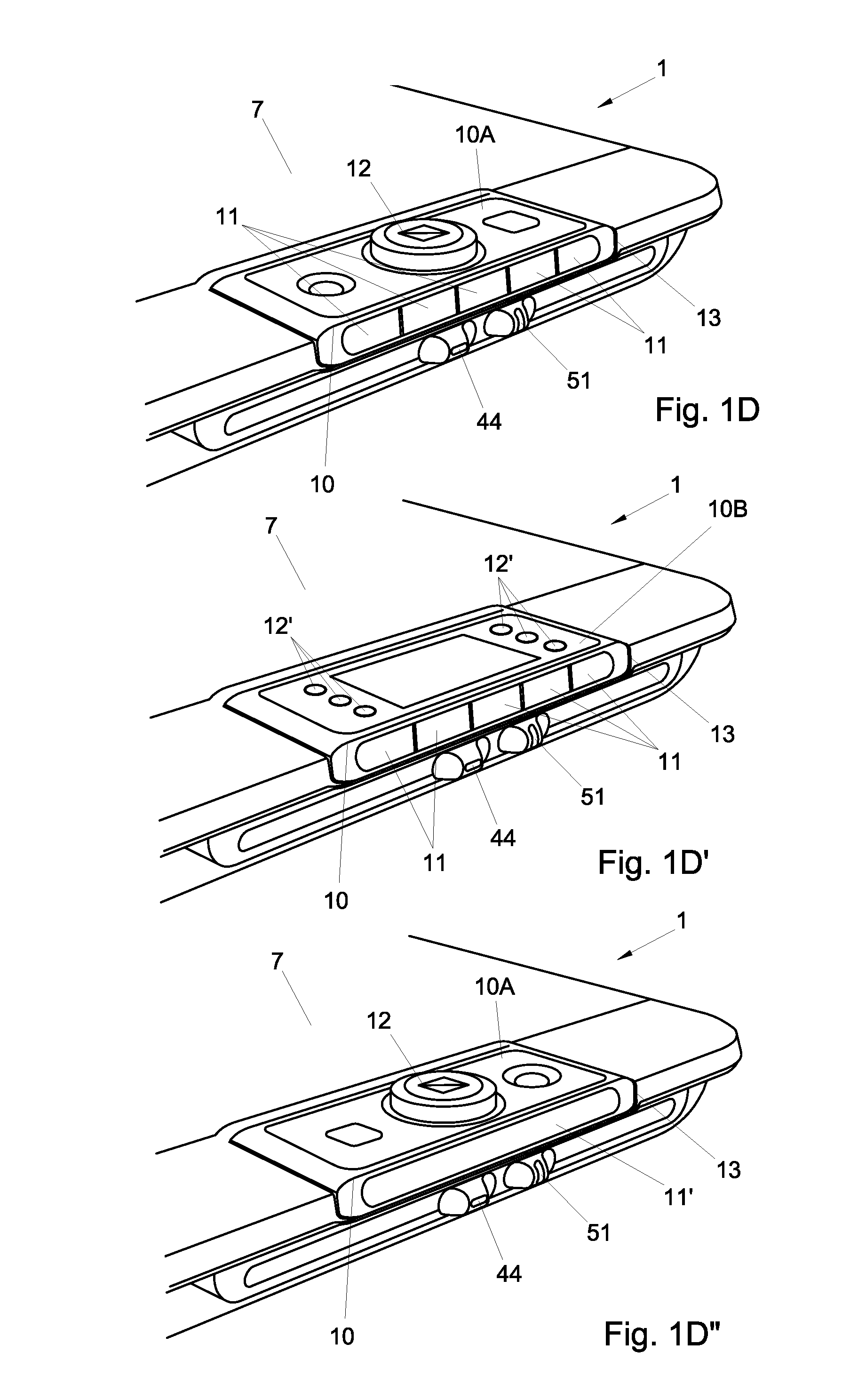
[0051]In FIG. 1A an embodiment of an object presenting unit 1 of a vision enhancing device according to the invention is shown without a table top. The object presenting unit 1 comprises a bottom plate 2 which can e.g. be placed on a desk top or other support surface (not-shown). An intermediate mid-table 3 is mounted on the bottom plate 2 so as to be displaceable back and forth in a first direction (indicated by the arrow FD in FIG. 4C) in a horizontal plane by means of for example a rail construction of which one rail part 4 is attached to the bottom plate 2 and the other rail part 5 is attached to the intermediate mid-table 3 (see FIG. 4C). As shown in e.g. FIG. 1A the object presenting unit 1 further comprises a table 6, which is mounted to the intermediate mid-table 3 so as to be displaceable back and forth in a second direction SD in a horizontal plane, said second direction SD being perpendicular to the first direction FD. In this manner the table 6 is displaceable in two ort...


PUM


Abstract

A Low Vision enhancing device for recording an object whereon text and/or at least one picture are visible and for displaying the recorded object on a screen, said vision enhancing device being provided with:
    • an object presenting unit comprising a bottom plate carrying a table for supporting an object to be displayed on a screen, said table being mounted to the bottom plate so as to be displaceable in at least opposite directions in a horizontal plane;
    • an upstanding stand attached to the bottom plate;
    • a light sensitive sensor mounted to the upstanding stand for obtaining recording signals of the object which signals are indicative for the text and/or the at least one picture of the object;
    • processing means for processing the recording signals into video signals; and
      • a screen preferably mounted to the upstanding stand, which screen, in use, is provided with the video signals for displaying an image of the recorded object on the screen; characterized in that the upstanding stand is arranged to be positioned at a left or right side of the light sensitive sensor and/or the screen if the device is viewed from a user position in front of the screen.

Description

BACKGROUND OF THE INVENTION[0001]The present invention relates to a vision enhancing device for recording an object whereon text and / or at least one picture are visible, and for displaying the recorded object on a screen, said vision enhancing device being provided with:[0002]an object presenting unit comprising a bottom plate carrying a table for supporting an object to be displayed on a screen, said table being mounted to the bottom plate so as to be displaceable in at least two opposite directions in a horizontal plane;[0003]an upstanding stand attached to the bottom plate;[0004]a light sensitive sensor mounted to the upstanding stand for obtaining recording signals of the object, which signals represent an image of text and / or at least one picture on the object;[0005]processing means for processing the recording signals into video signals; and[0006]a screen, which, in use, is provided with the video signals for displaying an image of the recorded object on the screen.[0007]Such ...

Claims


Application Information

Patent Timeline
IPC IPC(8): H04N5/235H04N5/225H04N5/232
CPCH04N5/235H04N5/2253H04N5/23293G09B21/008H04N1/195H04N1/19594H04N2201/0436H04N23/50H04N23/63H04N23/70H04N23/54
Inventor VAN HEES, LUKAS WILHELMUS
Owner OPTELEC DEV BV
Why Eureka
Try Eureka