Toner

a technology of toner and spherical paper, applied in the field of toner, can solve the problems of inability to maintain the quality of toner, the inability to meet the requirements of use, and the inability to achieve the effect of good preservation and fixing property, no density thinness or weakness, and no toner thinness or weakness

Active Publication Date: 2015-03-05
CANON KK
View PDF9 Cites 5 Cited by
  • Summary
  • Abstract
  • Description
  • Claims
  • Application Information

AI Technical Summary

Benefits of technology

[0011]It is an object of the present invention to provide a toner that has a good preservability and fixing property, and exhibits no density thinness or weakness at both ends of images even in long-term use.

Problems solved by technology

The use of the wax in a large amount, however, is liable to make the durability and the preservability of the toner inferior, so the simultaneous satisfaction of the both has been attempted conventionally by adjusting the balance between the fixing property, and the durability or preservability.
Even in the range of simultaneously satisfying the both, however, a new bad effect on images such as the image density thinness or weakness at image ends comes to occur.
Inside the scanner, the electrostatic latent image is formed by a polygon mirror rotating at a high speed, but the potentials at both ends of the electrostatic latent images drop due to a part of the polygon mirror being contaminated and the developing contrast is reduced to thereby cause the density thinness at both ends of the images.
On the other hand, since the polygon mirror in the scanner interior rotates at a high speed, the scanner interior pressure becomes negative and the scanner interior is liable to draw in surrounding air.
However, although an improvement in the fixing property by the use of these proposed waxes is recognized, the waxes are insufficient for the density thinness at both ends of images caused by the polygon mirror contamination, and an improvement is demanded.

Method used


Image

  • Toner
  • Toner
  • Toner

Examples


example 1

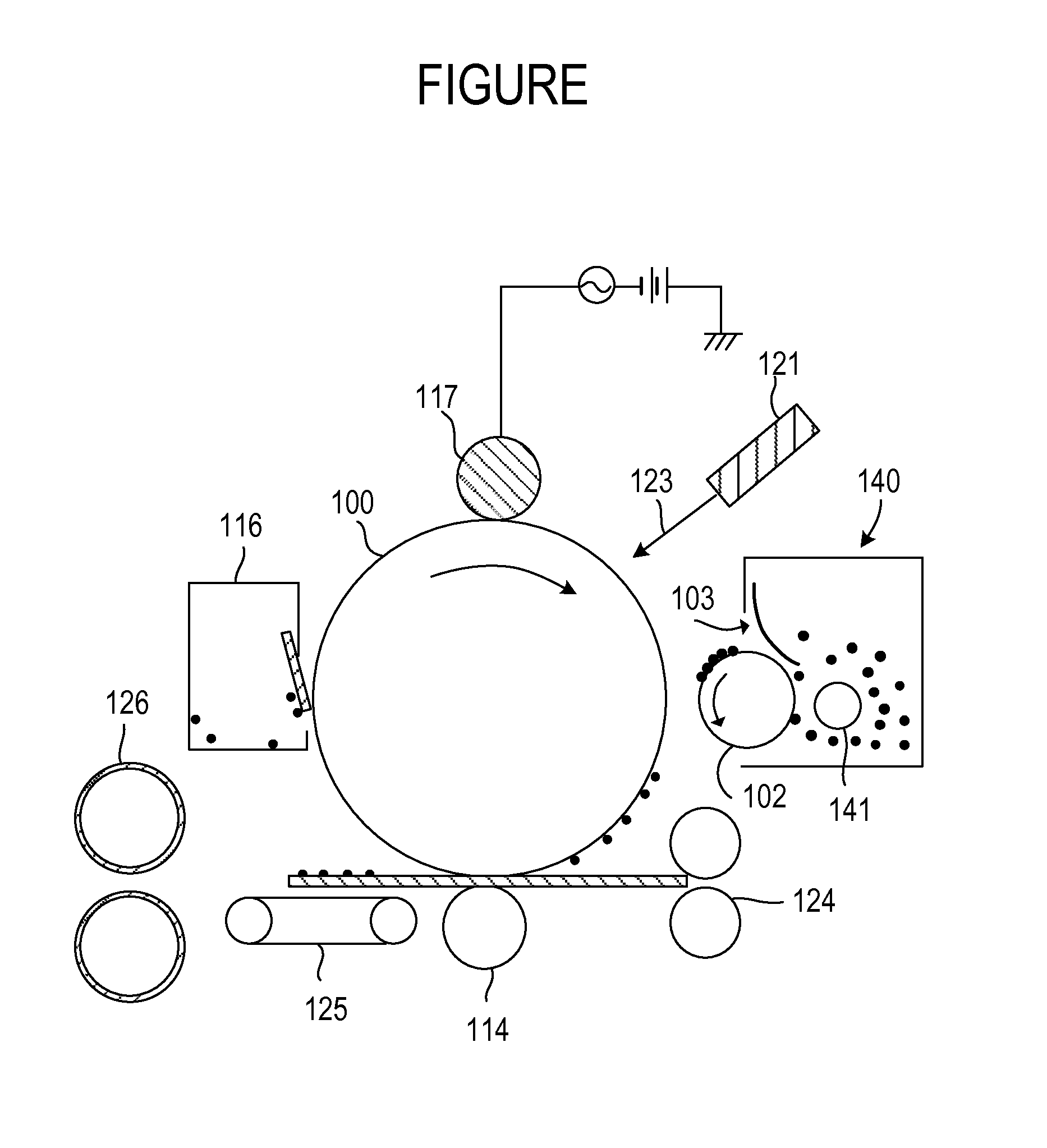
Image-Forming Apparatus

[0216]By using Laser Jet P1006 (manufactured by Hewlett-Packard Development Co.) as an image-forming apparatus, and using the toner 1, an image-forming test of 2,000 sheets printing horizontal lines of 4% in printing rate in a continuous mode was carried out under the normal temperature-normal humidity environment (23° C. / 60% RH). Here, during image-forming endurance, the image-forming test was carried out in a thick-paper mode. The thick-paper mode is a mode in which the temperature of a fixing assembly is set high, and an evaluation mode severe to the volatilization of the wax component.

[0217]After the finish of the image-forming test, in order to check whether any density reduction at both ends of images is caused, halftone images were printed out so that the reflection density of the image central part became 0.6, and the density difference between the image central part and ends of images was checked (first time). Further, the cartridge was replaced by a ...

examples 2 to 26

[0228]Image-forming tests were carried out as in Example 1, except for altering the toner 1 in Example 1 to the toners 2 to 26, respectively. As a result, any of those toners could provide images having a high image density before and after the durability test, and for those toners, the density reduction at both ends of the images, the fixing property and the preservability were at a non-problematic level. The evaluation results are shown in Table 7.


PUM


Abstract

A toner has toner particles including a binder resin, a colorant, an ester wax and a hydrocarbon wax; and inorganic fine particles. The ester wax includes an ester compound having a structure represented by formula (1): R1—CO—O—(CH2)x—O—OC—R2; or formula (2): R3—O—OC—(CH2)x—CO—O—R4. The ester wax includes an ester compound having a highest abundance rate in an amount of 40% to 80% by mass with respect to a total amount of the ester wax in a composition distribution. The ester wax has, in differential scanning calorimetry, a peak top temperature of an endothermic peak of 65° C. to 80° C. In differential scanning calorimetry, the toner has only one endothermic peak derived from the waxes. A relationship: 3.0≦(Tw−Tt)≦8.0 is satisfied.

Description

BACKGROUND OF THE INVENTION[0001]1. Field of the Invention[0002]The present invention relates to a toner used in a recording method utilizing electrophotography or the like.[0003]2. Description of the Related Art[0004]A large number of methods for electrophotography are known. An electrostatic latent image is formed on an electrostatic image bearing member (hereinafter, also referred to as “photosensitive member”) by generally utilizing a photoconductive substance and using various types of apparatus units. The latent image is then developed with a toner and made to be a visible image; and the resulting toner image is transferred on a recording medium such as paper as needed, and thereafter fixed on the recording medium by heat, pressure or the like to thereby obtain a copy. Image forming apparatuses using such electrophotography include copying machines and printers.[0005]Shift from analog to digital is occurring in these printers and copying machines, and the image quality is dema...

Claims


Application Information

Patent Timeline
Patent Type & Authority Applications(United States)
IPC IPC(8): G03G9/08
CPCG03G9/0825G03G9/08G03G9/08782G03G9/08797G03G9/09328G03G9/09364
Inventor MAGOME, MICHIHISASANO, TOMOHISAURATANI, KOZUE
Owner CANON KK
Why Eureka
Try Eureka