Circuit-terminal connecting device

a connecting device and circuit technology, applied in the direction of coupling device connection, printed circuit, electrical apparatus, etc., can solve the problems of inferior stiffness for locking the second housing, undeclared proportion of manipulable members, etc., and achieve the effect of large stiffness, reduced weight, and large engagemen

Inactive Publication Date: 2015-03-05
DAIICHI SEIKO CO LTD
View PDF8 Cites 21 Cited by
  • Summary
  • Abstract
  • Description
  • Claims
  • Application Information

AI Technical Summary

Benefits of technology

[0031]Further, in the circuit-terminal connecting device according to the present invention, each of the movable locking portions at the ends of the manipulatable member is operative to pass through the second metallic member of the second electrical connector to be supported by the second metallic member and the first metallic member of the first electrical connector is provided thereon with the fixed locking portion, so that each of the movable locking portions at the ends of the manipulatable member is supported by the second metallic member having relatively large stiffness to engage with the fixed locking portion provided on the first metallic member also having relatively large stiffness. Accordingly, even if a thickness of each of the first and second housings is reduces for miniaturization and reduction in weight of the first and second electrical connectors, each of the movable locking portions at the ends of the manipulatable member is able to be put in firm engagement with the fixed locking portion provided on the first metallic member so that the second housing is mechanically locked stably and reliably to the first housing.
[0032]Besides, with the circuit-terminal connecting device according to the present invention, for causing the movable locking portions at the ends of the manipulatable member to disengage respectively with the fixed locking portions provided on the first metallic member so that the second housing is released from the mechanical lock to the first housing, it is required only to shift the manipulatable member from the first station in which the manipulatable member keeps lying down on the second housing to the second station in which the manipulatable member keeps rising from the second housing. Accordingly, the second housing can be surely released from the mechanical lock to the first housing by means of simple and easy manipulation without using any specified tool or the like.

Problems solved by technology

Therefore, it is feared that the arm portion of the manipulatable member is undesirably subjected to plastic deformation so as not to restore appropriately to the original state when the manipulatable member is caused to restore not to be resiliently deformed after being once deformed resiliently.
That is, the rotating axis of the manipulatable member is not supported by any metallic member having relatively large stiffness but supported by the first housing made of insulating material inferior in stiffness for locking the first housing to the second housing.
Therefore, especially under a situation wherein a thickness of each of the first and second housings is reduces for miniaturization and reduction in weight of the first and second electrical connectors, it is feared that the rotating axis of the manipulatable member is unsurely or unstably supported by the outside wall portion of the first housing so as not to engage surely and reliably with the protrusion provided on the second housing.
Therefore, it is feared that the engaging portion of the manipulatable member is undesirably subjected to plastic deformation so as not to restore appropriately to the original state when the manipulatable member is caused to restore not to be resiliently deformed after being once deformed resiliently.
That is, the engaging portion of the manipulatable member having the locking end portion at its top end is not supported by any metallic member having relatively large stiffness but supported by the second housing made of insulating material inferior in stiffness for locking the second housing to the first housing.
Therefore, especially under a situation wherein a thickness of each of the first and second housings is reduces for miniaturization and reduction in weight of the first and second electrical connectors, it is feared that the engaging portion of the manipulatable member is unsurely or unstably supported by the outside wall portion of the second housing so that the locking end portion at the top end of the engaging portion is not able to engage surely and reliably with the engaging hole formed on the locking portion of the metallic member of the first electrical connector.

Method used


Image

  • Circuit-terminal connecting device
  • Circuit-terminal connecting device
  • Circuit-terminal connecting device

Examples


Embodiment Construction

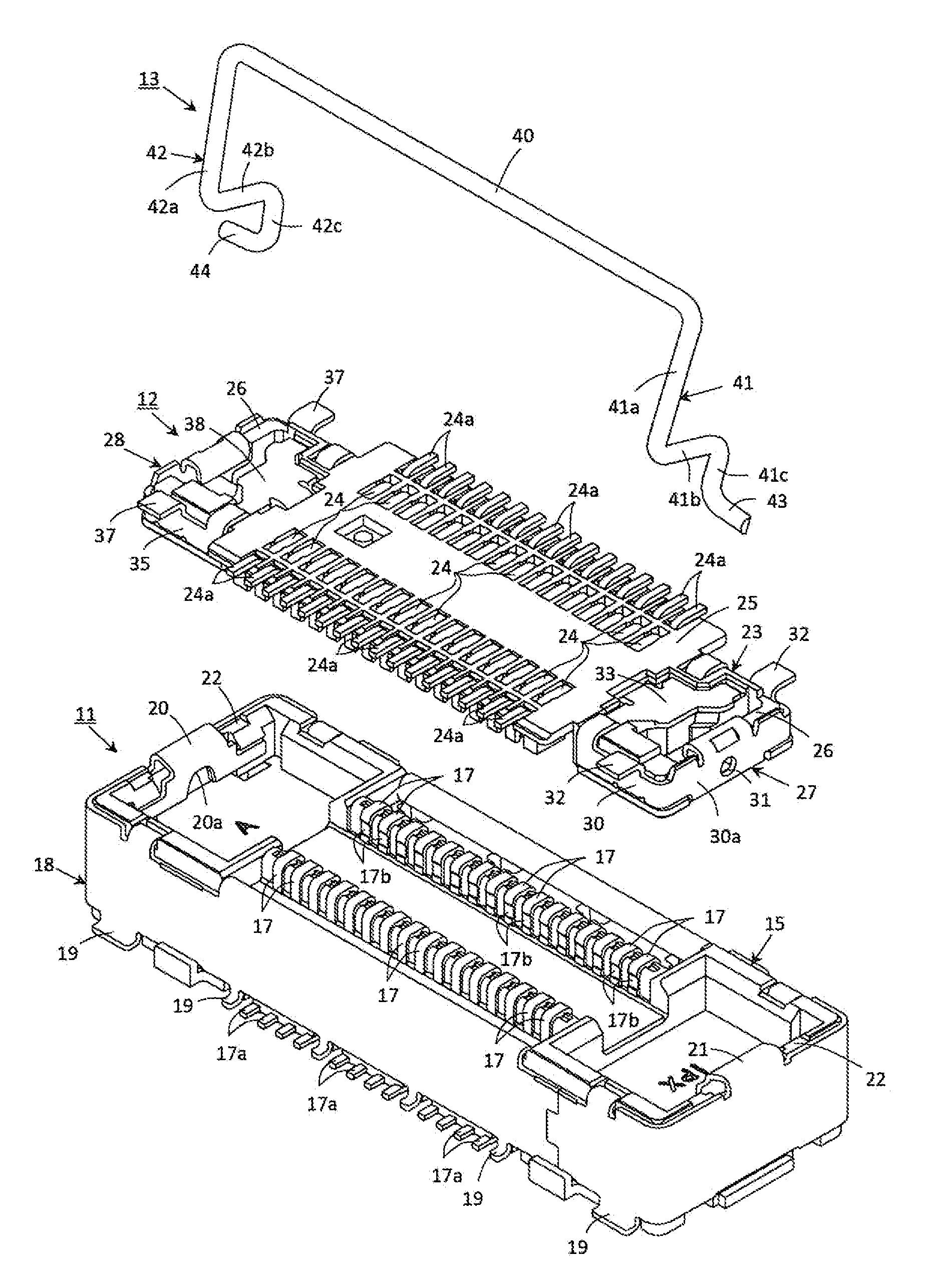
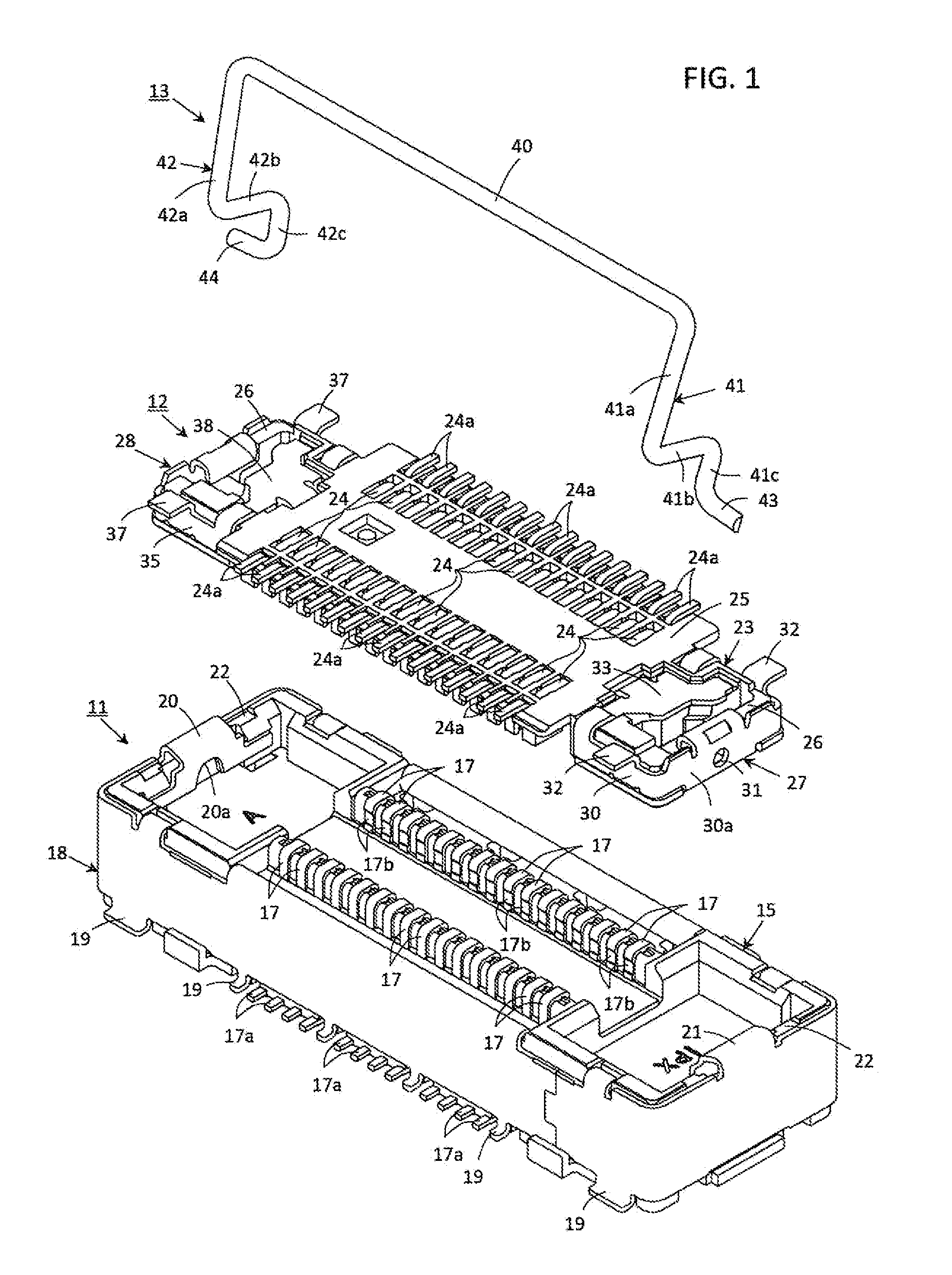
[0062]FIG. 1 shows a receptacle type connector 11 constituting a first electrical connector, a plug type connector 12 constituting a second electrical connector and a manipulatable member 13 each included in an embodiment of circuit-terminal connecting device according to the present invention which comprises the first electrical connector, the second electrical connector and the manipulatable member 13.

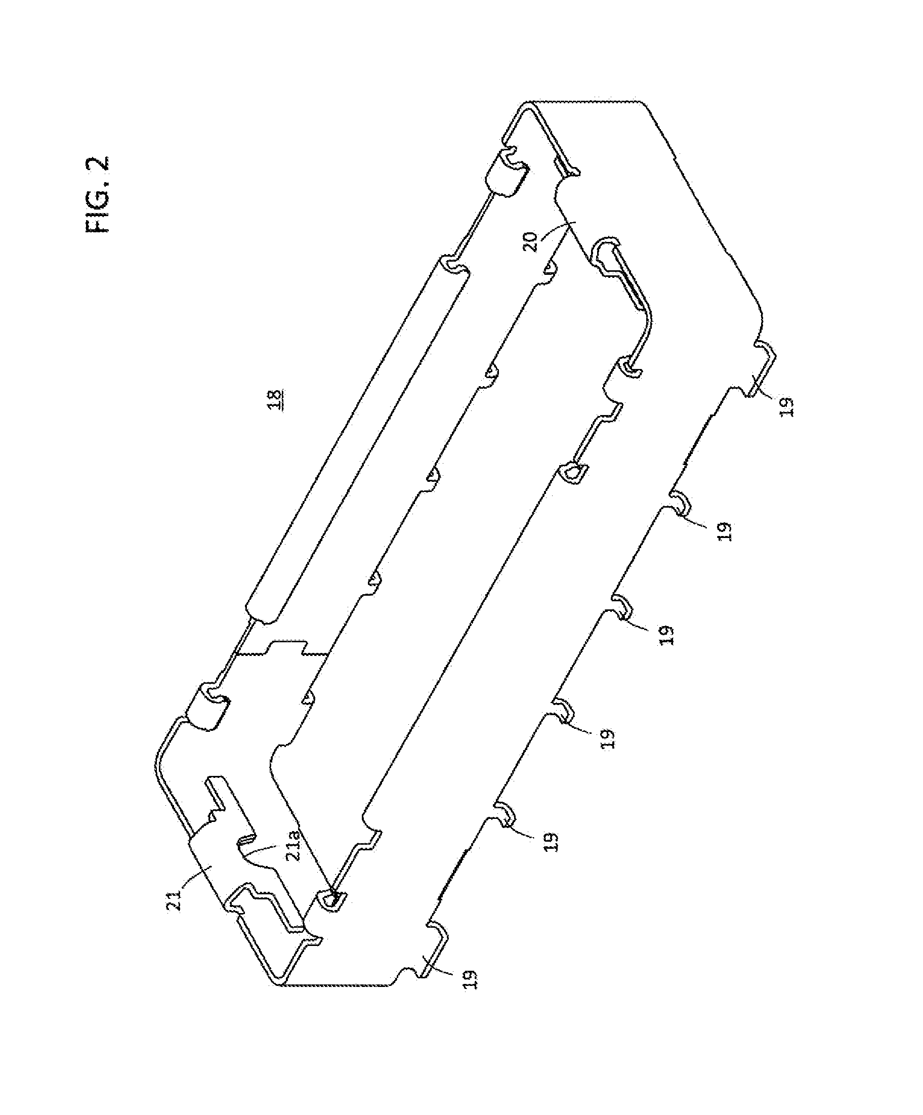
[0063]The receptacle type connector 11 shown in FIG. 1 has a housing 15 made of insulator such as plastics or the like to constitute a first housing. The housing 15 is mounted on a surface of a first circuit board 16, which is imaginarily shown with chain lines in FIG. 7 mentioned later, to be attached to the first circuit board 16 when the receptacle type connector 11 is put to practical use. The surface of the first circuit board 16 on which the housing 15 is mounted faces upward in FIG. 7 (hereinafter, referred to an upper surface of the first circuit board 16).

[0064]A plurality o...


PUM


Abstract

A circuit-terminal connecting device comprising a first connector having a first housing attached to a first circuit board provided thereon with first circuit-terminals and a first metallic member, a second connector having a second housing attached to a second circuit board provided thereon with second circuit-terminals and a second metallic member and a manipulatable member mounted on the second housing, wherein an end portion of the manipulatable member is formed into a movable locking portion supported by the second metallic member, the first metallic member is provided thereon with a fixed locking portion, and the manipulatable member is resiliently deformed for causing the movable locking portion to engage with the fixed locking portion so that the second housing is put in mechanical lock to the first housing when the second housing is put in engagement with the first housing for connecting the second circuit-terminals with the first circuit-terminals.

Description

BACKGROUND OF THE INVENTION[0001]1. Field of the Invention[0002]The present invention relates generally to a circuit-terminal connecting device, and more particularly to an improvement in a circuit-terminal connecting device which comprises first and second electrical connectors fixed respectively to first and second circuit boards including flexible printed circuit boards (FPCs) to be used for putting first and second groups of circuit-terminals provided respectively on the first and second circuit boards in mutual electrical connection under a condition wherein the first and second electrical connectors are coupled with each other so that the second circuit board is closely laid on top of the first circuit board.[0003]2. Description of the Prior Art Including Information Disclosed Under 37 CFR 1.97 and 37 CFR 1.98[0004]Various kinds of electric or electronic parts are built even in a relatively small-sized electronic apparatus such as a mobile phone or the like. A major part of th...

Claims


Application Information

Patent Timeline
Patent Type & Authority Applications(United States)
IPC IPC(8): H01R13/639H01R12/71
CPCH01R12/716H01R13/639H01R12/7005H01R12/7029
Inventor TAKEMOTO, MASATOSHI
Owner DAIICHI SEIKO CO LTD
Why Eureka
Try Eureka