Insulator and rotating electric machine

a technology of electric machines and insulation, which is applied in the direction of dynamo-electric machines, electrical equipment, supports/enclosements/casings, etc., can solve the problems of limited strength of insulation, difficult to provide miniaturized motors, and inability to densely wound coils

Inactive Publication Date: 2009-04-23
TOYOTA JIDOSHA KK
View PDF10 Cites 20 Cited by
  • Summary
  • Abstract
  • Description
  • Claims
  • Application Information

AI Technical Summary

Benefits of technology

[0017]The present invention can thus provide an insulator

Problems solved by technology

In the conventional techniques, however, an insulator's strength limits tension applied in winding a coi

Method used


Image

  • Insulator and rotating electric machine
  • Insulator and rotating electric machine
  • Insulator and rotating electric machine

Examples


Embodiment Construction

[0027]Hereinafter the present invention in embodiments will be described. Identical or corresponding components are identically denoted and may not be described repeatedly in detail.

[0028]If an embodiment described below refers to numbers, amounts and the like, the present invention is not necessarily limited in scope to such numbers, amounts or the like, unless otherwise specified. Furthermore, the embodiment describes components, which are not necessarily essential to the present invention, unless otherwise specified. Furthermore, if there is more than one embodiment hereinafter, each embodiment is originally intended to have a characteristic portion thereof combined with that of another embodiment, as appropriate, unless otherwise specified.

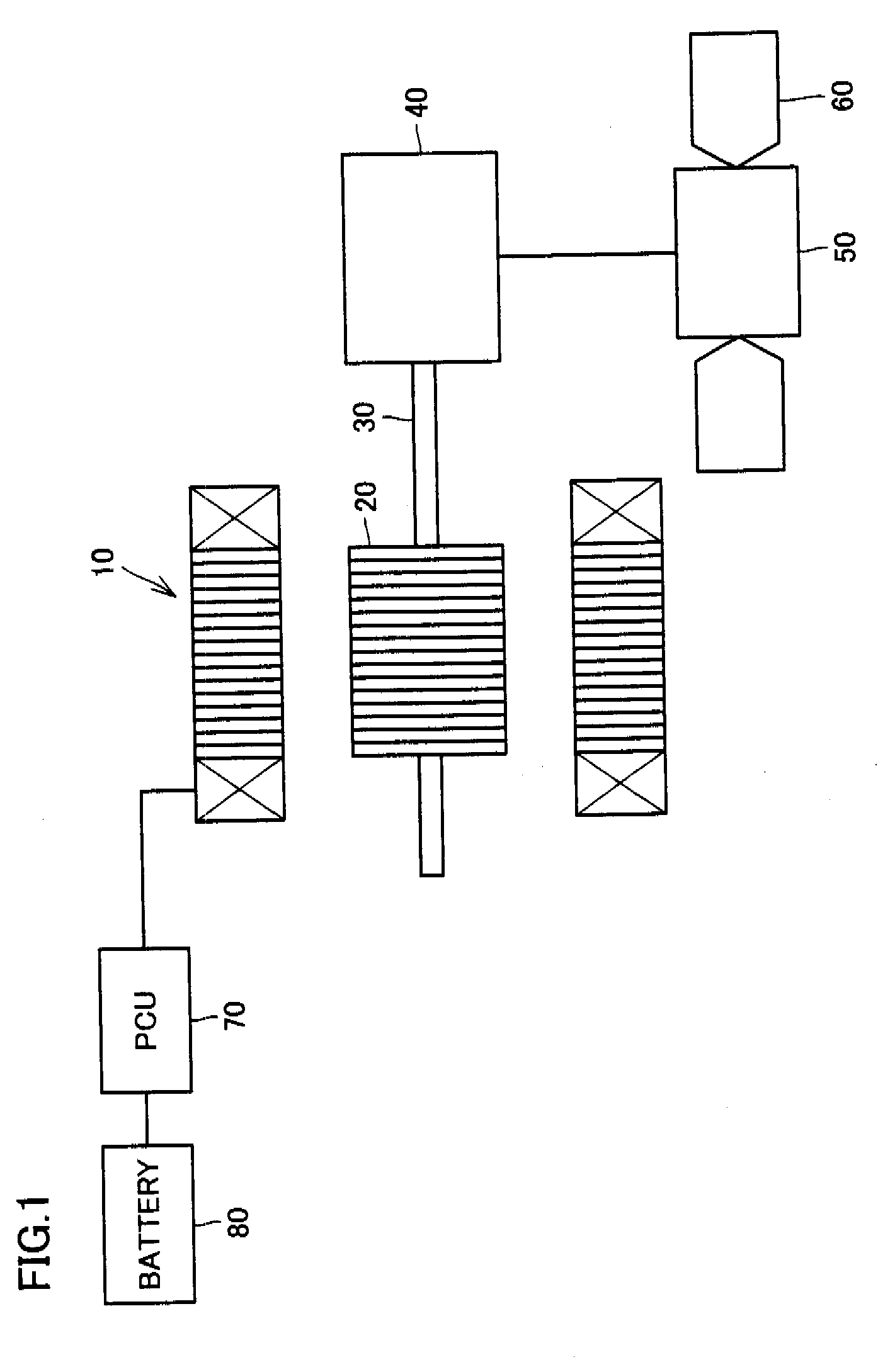
[0029]FIG. 1 shows a hybrid vehicle (HV) including a rotating electric machine according to one embodiment of the present invention. In the present specification, a “motored vehicle” is not limited to a hybrid vehicle and also includes for exa...


PUM


Abstract

An insulator allowing a coil to be wound with large tension exerted and a rotating electric machine having the insulator are provided. An insulator (140) can be attached to stator teeth (110) such that the insulator has a coil wound thereon, and the insulator (140) includes a first member implemented as a framework (940) forming a framework of the insulator (140) and a second member implemented as a sheath (950) providing an external surface of the insulator (140) and providing insulation, and the framework (940) is larger in stiffness than the sheath (950).

Description

TECHNICAL FIELD[0001]The present invention relates generally to insulators and rotating electric machines and particularly to insulators provided between a stator core and a stator coil and rotating electric machines having the insulator.BACKGROUND ART[0002]Conventionally, insulators have involved techniques, for example as disclosed in Japanese Patent Laying-Open Nos. 2004-48908 (Patent Document 1), 2002-51491 (Patent Document 2) and 2005-51998 (Patent Document 3).DISCLOSURE OF THE INVENTION[0003]In the conventional techniques, however, an insulator's strength limits tension applied in winding a coil. Accordingly the coil cannot be wound densely, and it has been difficult to provide miniaturized motors.[0004]The present invention has been made in view of such disadvantage as above and it contemplates an insulator allowing a coil to be wound densely and a rotating electric machine having the insulator.[0005]The present insulator is attachable to stator teeth while having a coil woun...

Claims


Application Information

Patent Timeline
IPC IPC(8): H02K3/34
CPCH02K3/522H02K2203/12H02K2203/09H02K5/225
Inventor TSUKASHIMA, HIROYUKI
Owner TOYOTA JIDOSHA KK
Why Eureka
Try Eureka