Synchronously self deploying boom

a boom and self-distribution technology, applied in the field of folding booms, can solve the problems of uncontrolled and thus unknown deployment trajectory, increase the mass, complexity, and difficulty of transporting, and achieve the effect of substantial bending stiffness and small volum

Inactive Publication Date: 2009-07-23
FOSTER-MILLER
View PDF99 Cites 21 Cited by
  • Summary
  • Abstract
  • Description
  • Claims
  • Application Information

AI Technical Summary

Benefits of technology

[0009]It is a further object of this invention to provide such a deployable boom which can be collapsed to a fairly small volume.
[0010]It is a further object of this invention to provide such a deployable boom including hinges which provide substantial bending stiffness orthogonal to the direction of deployment.

Problems solved by technology

Existing deployable structure joints have several limitations that either completely prevent them from being used in high precision deployable instruments or require additional launch mass to provide deployment actuation and post deployment locking.
Various deployment mechanisms add to the mass, expense and complexity of the structure and to the difficulty and expense of transporting it.
Uncontrolled deployments are very simple, but the trajectory of the deployment is uncontrolled and thus unknown.
The result can potentially lead to unsafe conditions when the boom impacts neighboring equipment during deployment.
The motors are expensive, heavy, and perform no useful function once the deployment is complete.
When the synchronously deployed boom relies on a motor or spring, stiffness can be limited, the motor adds weight to the system, and the result can be an imprecise deployment.

Method used


Image

  • Synchronously self deploying boom
  • Synchronously self deploying boom
  • Synchronously self deploying boom

Examples


Embodiment Construction

[0032]Aside from the preferred embodiment or embodiments disclosed below, this invention is capable of other embodiments and of being practiced or being carried out in various ways. Thus, it is to be understood that the invention is not limited in its application to the details of construction and the arrangements of components set forth in the following description or illustrated in the drawings. If only one embodiment is described herein, the claims hereof are not to be limited to that embodiment. Moreover, the claims hereof are not to be read restrictively unless there is clear and convincing evidence manifesting a certain exclusion, restriction, or disclaimer.

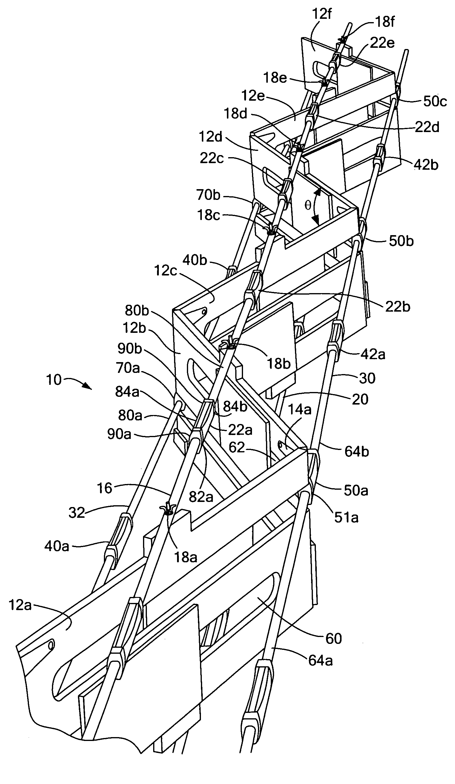
[0033]FIG. 1 shows an example of a boom 10 in accordance with the subject invention in its deployed state or configuration. Adjacent panels 12a and 12b are hinged together via hinges as shown for hinge 14a. Typically two spaced hinges pivotably connect adjacent panels. Thus, panel 12a is hinged to panel 12b which is hinged ...


PUM


Abstract

A deployable boom with adjacent panels hinged together typically in an end to end configuration. A first longeron is attached to at least two panels and a second longeron is also attached to at least two panels. Each longeron includes a self locking hinge between adjacent panels.

Description

FIELD OF THE INVENTION[0001]This subject invention relates to a foldable boom and other similar structures.BACKGROUND OF THE INVENTION[0002]Optical and other instruments deployed in outer space require a precise and stable structural platform. In some prior mechanically deployed structures, components are moved from their stored position into their final operational position by some type of an actuator and then locked into place with a deployment latch. Existing deployable structure joints have several limitations that either completely prevent them from being used in high precision deployable instruments or require additional launch mass to provide deployment actuation and post deployment locking.[0003]Recently, foldable truss members have been developed so that a truss structure can be collapsed and compactly packaged to save space during delivery and then released to expand and return to their original shape in orbit. Various deployment mechanisms add to the mass, expense and com...

Claims


Application Information

Patent Timeline
Patent Type & Authority Applications(United States)
IPC IPC(8): B64G1/22B66C23/42
CPCB66C23/68B64G1/222
Inventor WARREN, PETER A.DOBSON, BENJAMIN J.SILVER, MARK J.
Owner FOSTER-MILLER
Why Eureka
Try Eureka