Positive retention lock ring for tubing hanger

a technology of lock ring and tubing hanger, which is applied in the direction of drilling casings, drilling pipes, borehole/well accessories, etc., can solve the problems of lock ring, tubing hanger axial movement, seal may need to be removed,

Inactive Publication Date: 2015-03-12
VETCO GRAY LLC
View PDF4 Cites 7 Cited by
  • Summary
  • Abstract
  • Description
  • Claims
  • Application Information

AI Technical Summary

Benefits of technology

[0007]Embodiments of this disclosure relate primarily to a tubing hanger lock ring that can be positively retained after a tubing hanger seal is set. Systems and methods of this disclosure can allow for changing the seal without compromising the locking capability of the tubing hanger to the wellhead. The lock ring can stay engaged even when the seal is removed.
[0008]In an embodiment of this disclosure, a wellhead assembly includes a wellhead housing. The wellhead housing has a bore with an axis and an annular lock groove on an inner diameter surface of the bore. A wellbore member is concentrically located within the bore of the wellhead housing, defining an annulus between the wellbore member and the wellhead housing. The wellbore member has an upward facing shoulder. An annular lock ring is positioned in the annulus. The annular lock ring has an outer diameter profile for engaging the lock groove and is radially expandable from an unset position to a set position. The set position prevents upward axial movement of the wellbore member relative to the wellhead housing. The lock ring has an inward and upward facing tapered surface. An energizing ring is positioned in the annulus above the lock ring. The energizing ring is axially movable from an upper position to a lower position, and has an outward and downward facing lower tapered surface that engages the tapered surface of the lock ring to push the lock ring outward to the set position as the energizing ring moves downward. A retainer is in selective engagement with the energizing ring. The retainer limits axial upward movement of the energizing ring relative to the wellbore member, retains the annular lock in the set position, and prevents axial upward movement of the wellbore member relative to the wellhead housing.
[0009]In an alternate embodiment of this disclosure, a wellhead assembly includes a wellhead housing, the wellhead housing having a bore with an axis and an annular lock groove on an inner diameter surface of the bore. A wellbore member is concentrically located within the bore of the wellhead housing defining an annulus between the wellbore member and the wellhead housing. The wellbore member has an upward facing shoulder. An annular lock ring is positioned in the annulus. The annular lock ring is located on the upward facing shoulder and has an outer diameter profile for engaging the lock groove. The annular lock ring is radially expandable from an unset position to a set position, the set position preventing upward axial movement of the wellbore member relative to the wellhead housing. The lock ring has an inward and upward facing tapered surface. An energizing ring is positioned in the annulus above the lock ring. The energizing ring is axially movable from an upper position to a lower position. The energizing ring has an outward and downward facing lower tapered surface that engages the upward facing tapered surface of the lock ring to push the lock ring outward to the set position as the energizing ring moves downward. A retainer is carried by the wellbore member. The retainer is biased radially outward and when the annular lock ring is in the set position, the energizing ring is retained between the upward facing shoulder of the wellbore member and the retainer, preventing axial upward movement of the wellbore member relative to the wellhead housing.

Problems solved by technology

A lockdown ring, however, is required to lock the tubing hanger in place when the tubing hanger is subjected to high pressures.
Those high pressures can cause the tubing hanger to move axially upward.
Unfortunately, the seal may need to be removed from time to time.
High pressure in the wellbore can cause the tubing hanger or the energizing ring to shift upward when the seal has been removed.
The nature of the energizing ring, and the tapered surface on the energizing ring, means that any upward movement of the energizing ring can allow the lockdown ring to move radially inward, thus weakening the lock.

Method used


Image

  • Positive retention lock ring for tubing hanger
  • Positive retention lock ring for tubing hanger
  • Positive retention lock ring for tubing hanger

Examples


Embodiment Construction

[0018]The present invention will now be described more fully hereinafter with reference to the accompanying drawings which illustrate embodiments of the invention. This invention may, however, be embodied in many different forms and should not be construed as limited to the illustrated embodiments set forth herein. Rather, these embodiments are provided so that this disclosure will be thorough and complete, and will fully convey the scope of the invention to those skilled in the art. Like numbers refer to like elements throughout, and the prime notation, if used, indicates similar elements in alternative embodiments.

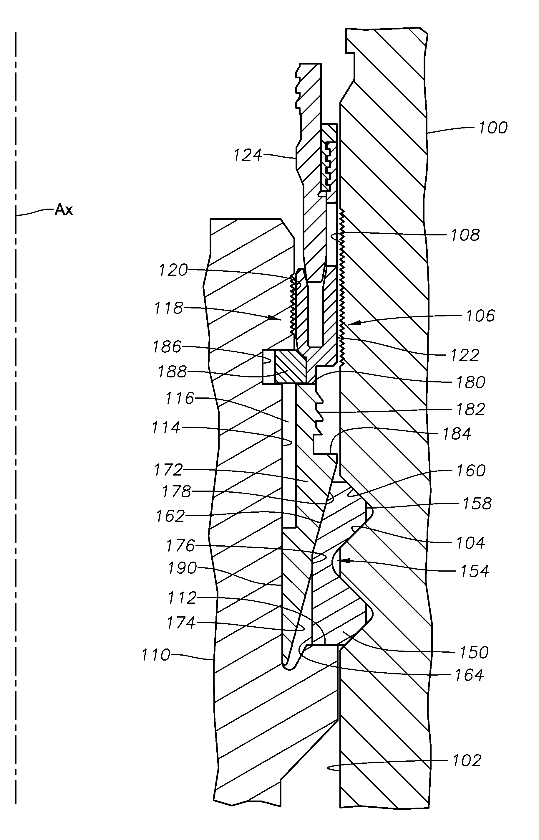
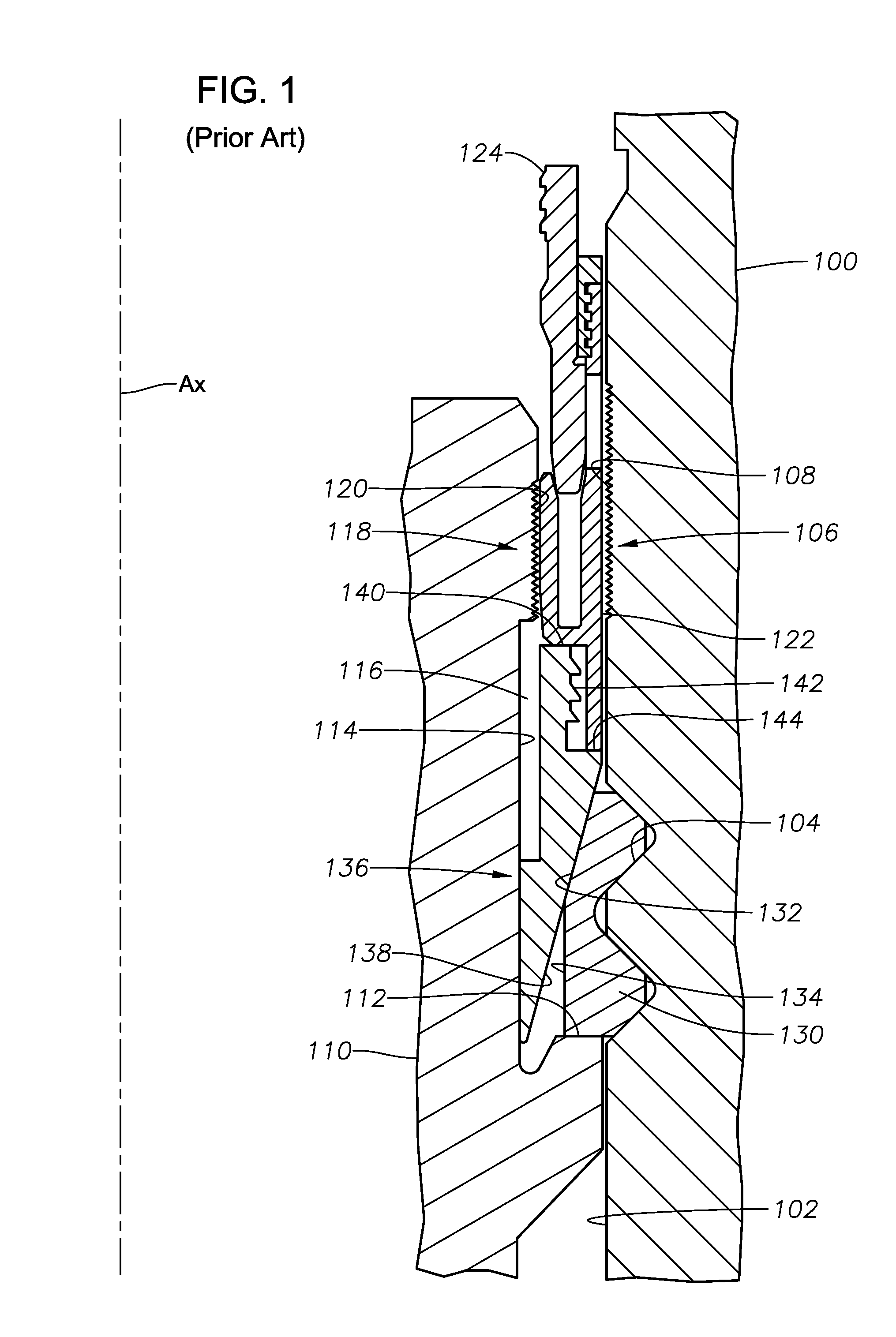
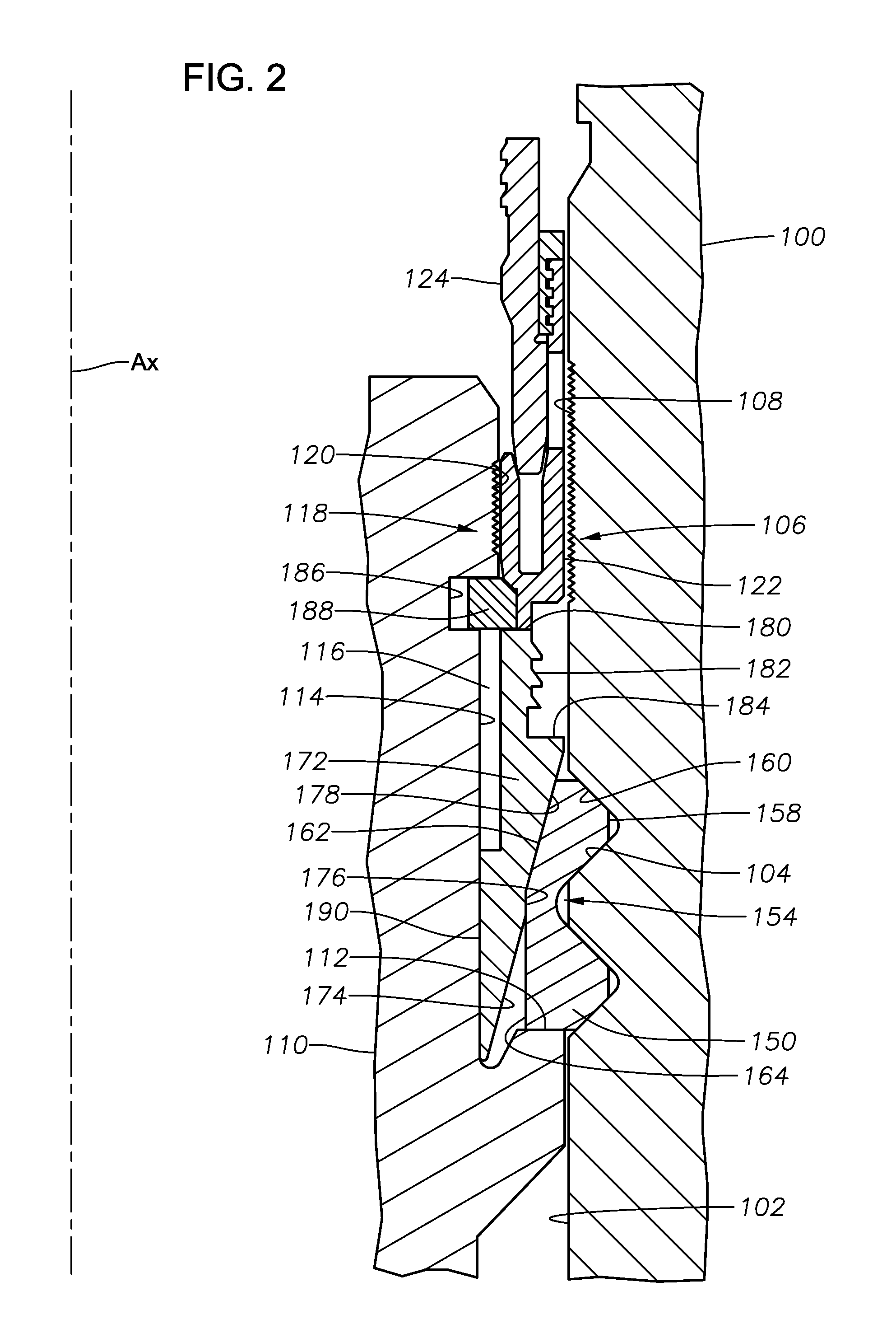
[0019]Referring to FIG. 1, a wellhead housing 100 is shown. Wellhead housing 100 has a bore 102 with a central axis Ax. Annular lock ring groove 104 is located on an inner diameter surface of the bore 102. Lock ring groove 104 can include one or more annular grooves to define a lock ring groove profile. The individual grooves can each have the same shape or can have a di...


PUM


Abstract

A wellhead assembly includes a wellhead housing with a bore and an annular lock groove on an inner diameter surface of the bore. A wellbore member is concentrically located within the bore of the wellhead housing, defining an annulus between the wellbore member and the wellhead housing. An annular lock ring is positioned in the annulus. The annular lock ring has an outer diameter profile for engaging the lock groove and is radially expandable from an unset position to a set position. An energizing ring is positioned in the annulus to push the lock ring outward to the set position as the energizing ring moves downward. A retainer selectively engages the energizing ring and limits axial upward movement of the energizing ring relative to the wellbore member, retains the annular lock in the set position, and prevents axial upward movement of the wellbore member relative to the wellhead housing.

Description

CROSS REFERENCE TO RELATED APPLICATION[0001]This application is a continuation-in-part of and claims priority to and the benefit of U.S. patent application Ser. No. 13 / 468,378, titled “Positive Retention Lock Ring for Tubing Hanger,” filed May 10, 2012, the full disclosure of which is hereby incorporated herein by reference in its entirety for all purposes.BACKGROUND OF THE DISCLOSURE[0002]1. Field of the Disclosure[0003]The present disclosure relates in general to mineral recovery wells, and in particular to lockdown rings for retaining wellbore members in a housing.[0004]2. Brief Description of Related Art[0005]Tubing hangers are landed on a shoulder in a wellhead. The shoulder prevents downward movement of the tubing hanger in the wellhead. The weight of the tubing hanger and the tubing hanging from the tubing hanger can prevent upward movement of the tubing hanger under some circumstances. A lockdown ring, however, is required to lock the tubing hanger in place when the tubing h...

Claims


Application Information

Patent Timeline
Patent Type & Authority Applications(United States)
IPC IPC(8): E21B19/06E21B33/04
CPCE21B33/0422E21B19/06E21B33/04
Inventor DUONG, KHANH ANHHUNTER, RICK C.
Owner VETCO GRAY LLC
Why Eureka
Try Eureka