
Apparatus, System, and Method for Mobile, Low-Cost Headset for 3D Point of Gaze Estimation

a technology of 3d point and eye, applied in the field of 3d point of eye apparatus, can solve the problems of ineffectiveness of some inability to use traditional input methods, and inability to meet the needs of users with physical impairment, etc., and achieve the effect of limiting the widespread use of technology and limiting the availability of technology

Active Publication Date: 2015-03-12
BOARD OF RGT THE UNIV OF TEXAS SYST
View PDF8 Cites 46 Cited by
  • Summary
  • Abstract
  • Description
  • Claims
  • Application Information

AI Technical Summary

Benefits of technology

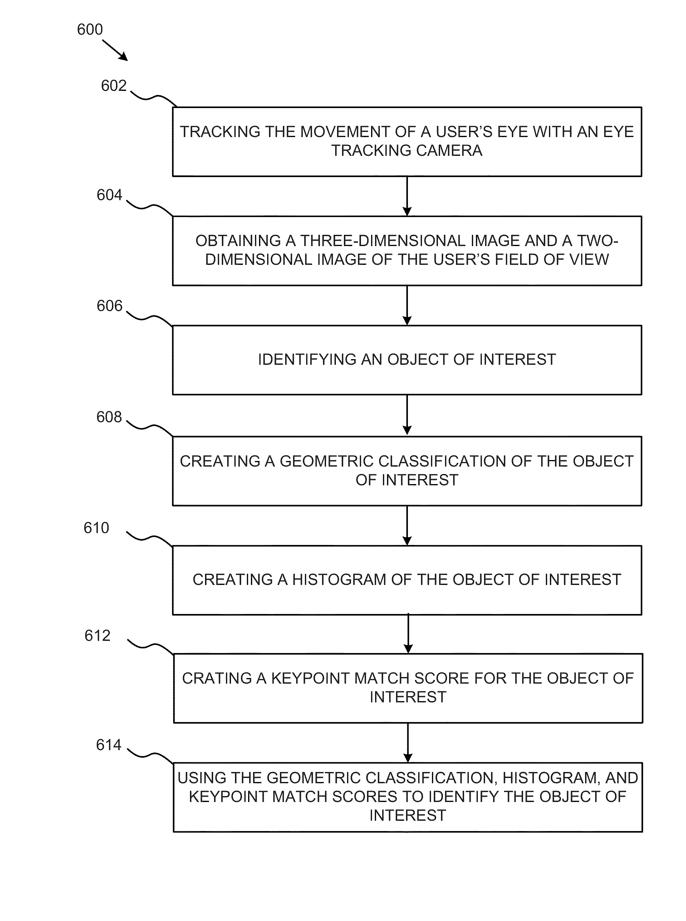
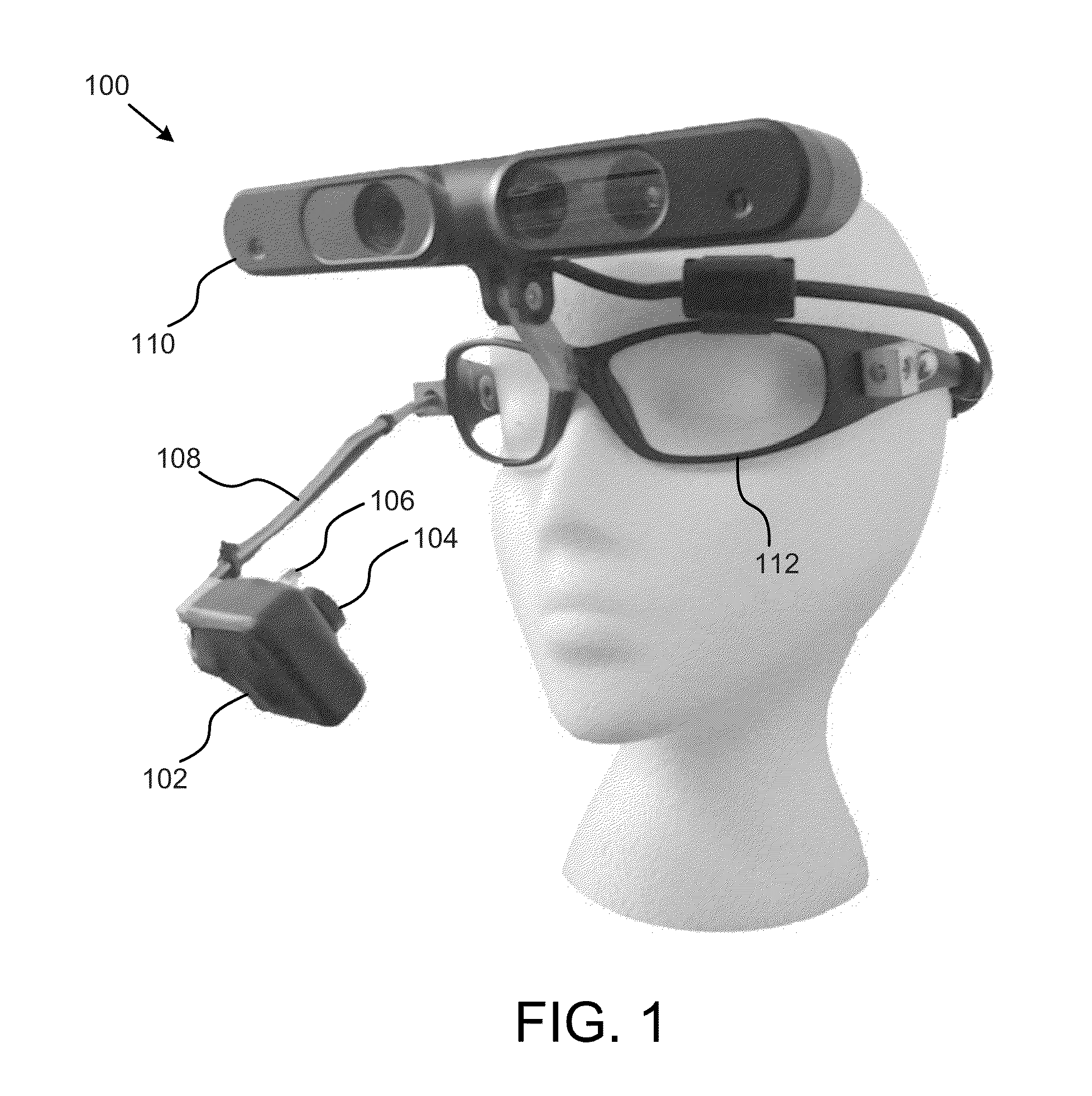
The patent describes a point of gaze apparatus that uses an eye tracking camera to track the movement of a user's eye and create a three-dimensional image and a two-dimensional image of the user's point of gaze. The apparatus can identify objects in the user's eye using information from the eye tracking camera and the scene camera. The apparatus can be mounted on a wearable headset or glasses and can be used in various applications such as gaming or augmented reality. The technical effects of this patent include improved accuracy in identifying the user's point of gaze and the ability to track the user's eye movements in real-time.

Problems solved by technology

Traditional input methods, such as the keyboard and mouse, are not practical in many situations and can be ineffective for some users with physical impairments.
While the utility of gaze interaction in a variety of applications has been demonstrated, the availability of the technology has been a limiting factor in more widespread use.
Due to the relatively high monetary cost and proprietary nature associated with commercial eye tracking equipment and software, several low-cost solutions have been developed using inexpensive on-the-shelf components.
This approach gives the 3D PoG relative to the user's frame of reference, but does not provide a mapping of this point to the environment in which the user is present.
While multi-camera approaches such as these provide a 3D PoG, their use is limited by increased uncertainty at increasing PoG depths.
Another limiting factor is the scene camera, which is generally a standard 2D camera that does not provide any 3D information of the environment itself.

Method used


Image

  • Apparatus, System, and Method for Mobile, Low-Cost Headset for 3D Point of Gaze Estimation
  • Apparatus, System, and Method for Mobile, Low-Cost Headset for 3D Point of Gaze Estimation
  • Apparatus, System, and Method for Mobile, Low-Cost Headset for 3D Point of Gaze Estimation

Examples


example

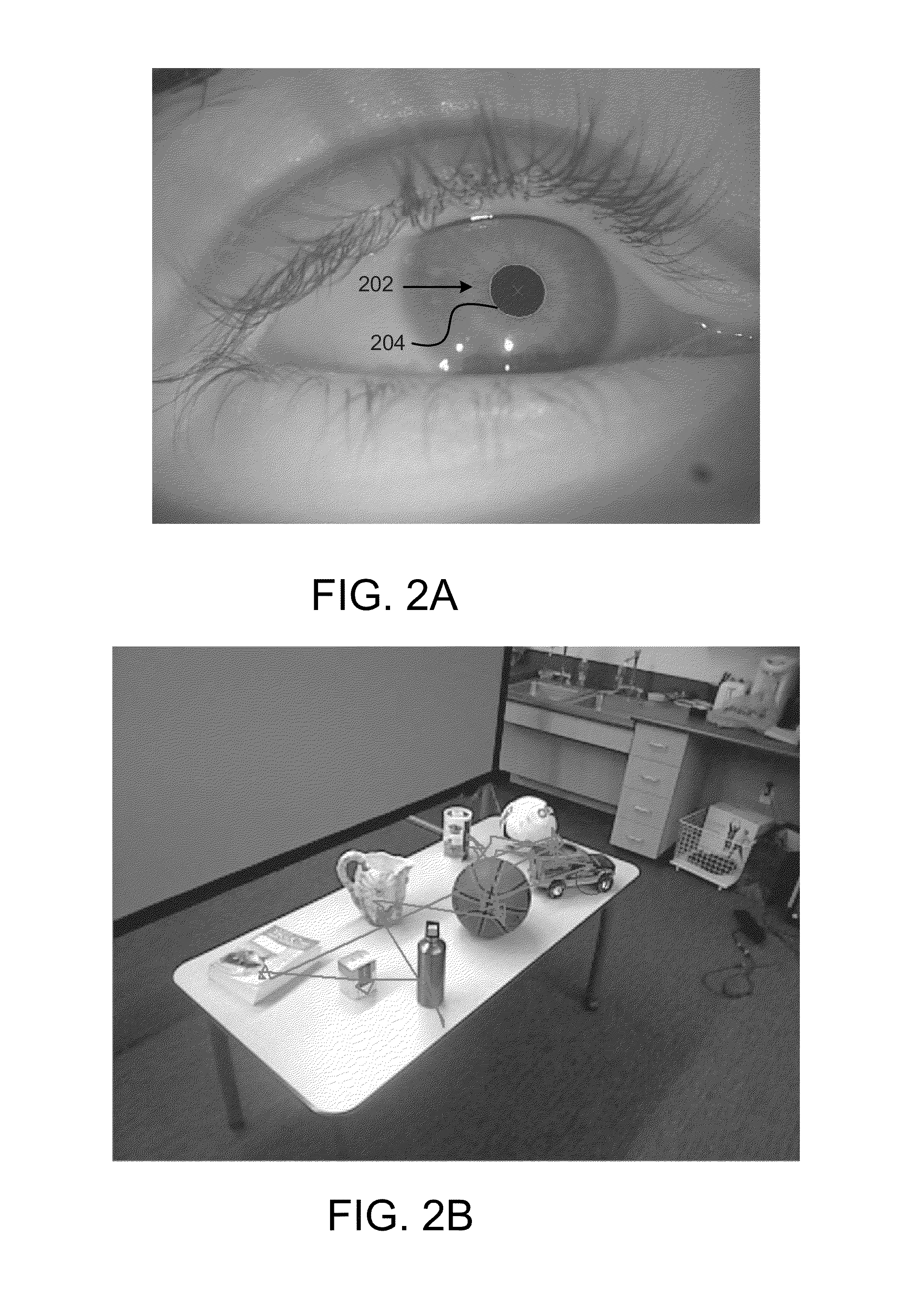
[0061]Referring to FIG. 5, to assess the ability of the system to identify the object gazed upon by the user 502, we created an experiment to reproduce a typical usage application in which the user is seated at a table and desires assistance with an item 504 on the table. The user might, for example, desire some water from a pitcher on the table, but be unable to reach for the object or request assistance through verbal means or gesturing.

[0062]To this end, we used the system software to create a knowledge base of known objects and placed an assortment of test items on the table to evaluate the system's ability to estimate the user's point of gaze, use that information to isolate the object of interest, and perform successful identification.

Experimental Setup

[0063]During our experiment, a participant 502 sat in multiple positions in front of a table with an assortment of objects placed on top. They were free to move their head, eyes, and body. We instructed the participant to focus ...


PUM


Abstract

An apparatus, system, and method for a mobile, low-cost headset for 3D point of gaze estimation. A point of gaze apparatus may include an eye tracking camera configured to track the movements of a user's eye and a scene camera configured to create a three-dimensional image and a two-dimensional image in the direction of the user's gaze. The point of gaze apparatus may include an image processing module configured to identify a point of gaze of the user and identify an object located at the user's point of gaze by using information from the eye tracking camera and the scene camera.

Description

RELATED APPLICATION[0001]This application claims priority to U.S. Provisional Patent Application 61 / 876,038 entitled “Apparatuses, System, and Method for Mobile, Low-Cost Headset for 3D Point of Gaze Estimation,” and filed on Sep. 10, 2013, the entire contents of which are incorporated herein by reference without disclaimer.STATEMENT REGARDING FEDERALLY-SPONSORED RESEARCH[0002]This invention was made with government support under grant numbers CNS 0923494, CNS 1035913, and IIS 1238660 awarded by the National Science Foundation. The government has certain rights in the invention.BACKGROUND OF THE INVENTION[0003]1. Field of Invention[0004]This invention relates to 3D point of gaze apparatus and more particularly relates to an apparatus system and method for mobile, low-cost, head-mounted, 3D point of gaze estimation.[0005]2. Description of Related Art[0006]Eye gaze based interaction has many useful applications in human-machine interfaces, assistive technologies, and multimodal system...

Claims


Application Information

Patent Timeline
Patent Type & Authority Applications(United States)
IPC IPC(8): G06F3/01G06K9/62G06K9/00
CPCG06F3/013G06K9/6212G06K9/00624G06K9/00604G06V40/19G06V10/758G06V10/757
Inventor MCMURROUGH, CHRISTOPHER D.
Owner BOARD OF RGT THE UNIV OF TEXAS SYST
Learn More