
Stereolithography machine with improved optical unit

a technology of optical unit and stereolithography machine, which is applied in the field of stereolithography machine, can solve the problems of irregular edges, mechanical devices used to move light beams, and inconvenient to obtain objects with irregular edges, so as to reduce machine maintenance costs, simplify construction, and reduce the effect of cos

Active Publication Date: 2015-03-12
DWS SRL
View PDF4 Cites 5 Cited by
  • Summary
  • Abstract
  • Description
  • Claims
  • Application Information

AI Technical Summary

Benefits of technology

This patent describes a way to quickly and easily light up an entire surface using a single exposure. This is made possible by using matrices of mirrors that can light up the entire surface at the same time. This technique also makes it easy to replace the optical unit during use, which can save money on maintenance costs.

Problems solved by technology

However, the matrices of mirrors have limited definition, with the inconvenience that objects with irregular edges are obtained.
A further drawback of the systems mentioned above lies in that the image they generate has uniform luminous intensity on its entire surface.
Therefore, this leads to the inconvenience that said systems do not allow light power to be modulated in the different areas of the reference surface.
This embodiment poses the drawbacks that the movements of the light beam are rather slow and that, furthermore, the mechanical device used to move the light beam runs the risk of breaking and therefore needs a certain amount of maintenance.
The above mentioned alignment operation poses the drawback that it is particularly complex and increases the cost of the stereolithography machine.
Said drawback occurs also in the case where, during use, one or both mirrors break, with the consequence that it is necessary to replace them and align them correctly.
A further drawback is represented by the fact that galvanometric mirrors are relatively expensive, which considerably affects the cost of the stereolithography machine.
An optical unit based on galvanometric mirrors poses the further drawback of being relatively bulky.
The high cost and large size make the stereolithography machine unsuitable for small series applications, which might be required by small craftman's businesses.
Furthermore, galvanometric mirrors have some mechanical components that are subject to wear and therefore limit their advantages compared to the mechanical movement devices mentioned above.

Method used


Image

  • Stereolithography machine with improved optical unit
  • Stereolithography machine with improved optical unit
  • Stereolithography machine with improved optical unit

Examples


Embodiment Construction

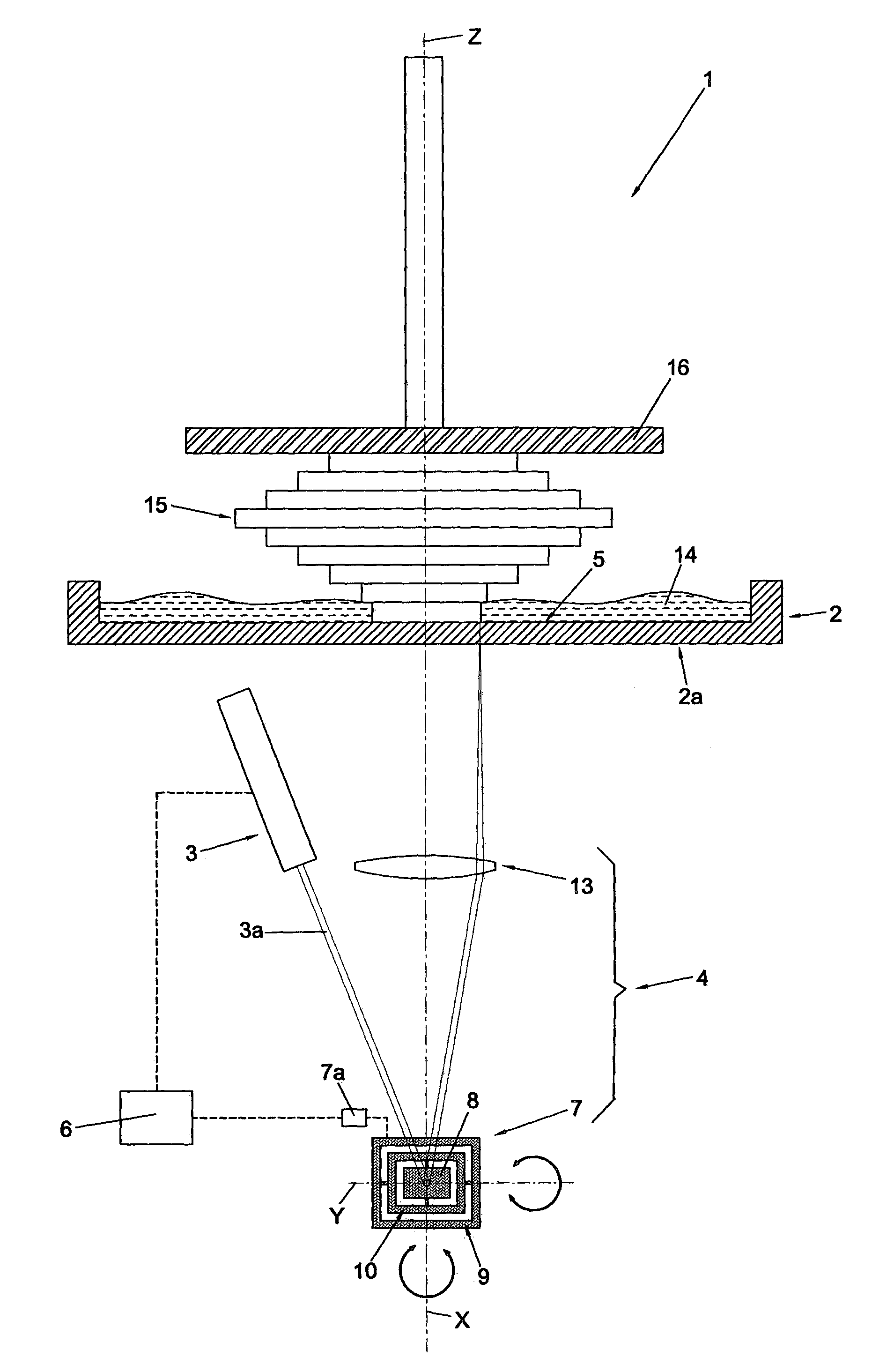
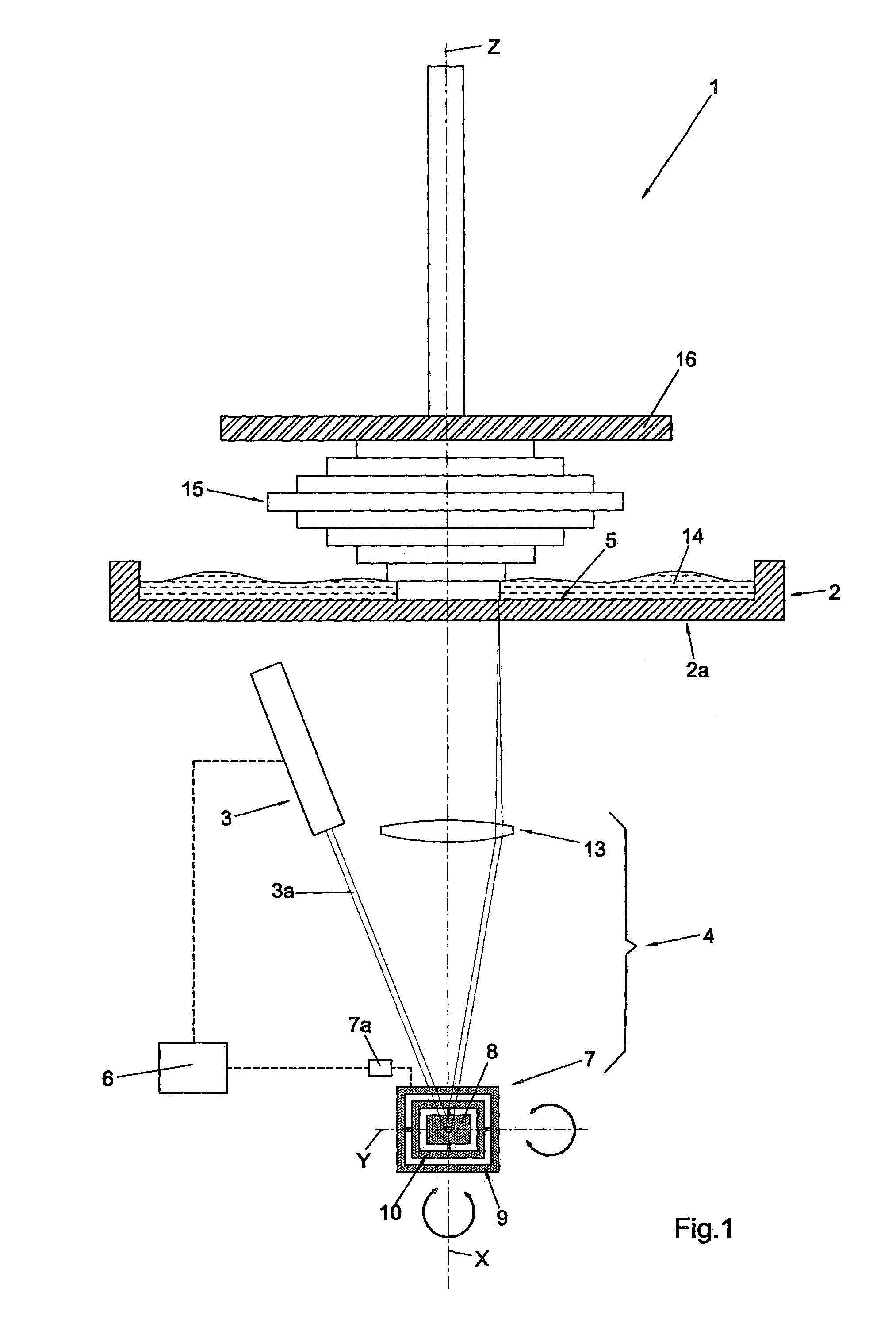
[0047]The stereolithography machine that is the subject of the invention, indicated as a whole by 1 in FIG. 1, makes it possible to produce a three-dimensional object 15 by means of a process according to which a plurality of layers are superimposed to one another, said layers being obtained through the selective exposure of a fluid substance 14 to predefined radiation 3a suited to solidify it. Preferably, said fluid substance 14 is a liquid light-sensitive resin and the predefined radiation 3a is a laser light with frequency in the field of the visible or ultraviolet.

[0048]Obviously, in construction variants of the invention, the fluid substance 14 can be of any kind, liquid or paste, provided that it is suited to solidify when exposed to predefined radiation 3a.

[0049]Analogously, said source 3 of radiation 3a can emit a type of radiation 3a that is different from the one mentioned above, provided that it can solidify the fluid substance 14.

[0050]The stereolithography machine 1 co...


PUM

PropertyMeasurementUnit
volumeaaaaaaaaaa
transparentaaaaaaaaaa
timeaaaaaaaaaa

Abstract

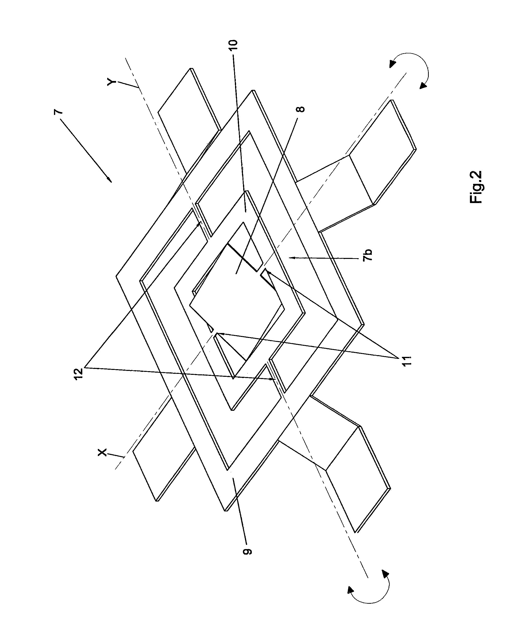
Stereolithography machine (1) comprising: a container (2) for a fluid substance (14); a source (3) of predefined radiation (3a) suited to solidify the fluid substance (14); an optical unit (4) suited to direct the radiation (3a) towards a reference surface (5) in the fluid substance (14); a logic control unit (6) configured to control the optical unit (4) and / or the source (3) so as to expose a predefined portion of the reference surface (5). The optical unit (4) comprises a micro-opto-electro-mechanical system (MOEMS) (7) provided with a mirror (8) associated with actuator means (7a) for the rotation around at least two rotation axes (X, Y) incident on and independent of each other, arranged so that it can direct the radiation (3a) towards each point of the reference surface (5) through a corresponding combination of the rotations around the two axes (X, Y).

Description

CROSS REFERENCE TO RELATED APPLICATIONS[0001]This application claims priority to PCT Application No. PCT / IB2012 / 002789, filed Dec. 24, 2012 and to Italian Application No. VI 2011A00333 filed Dec. 23, 2011, both of which are incorporated by reference herein in their entirety.BACKGROUND AND SUMMARY OF THE INVENTION[0002]The invention concerns a stereolithography machine of the type suitable for making three-dimensional objects by means of a plurality of superimposed layers, wherein each layer is obtained through the selective solidification of a fluid substance in the areas corresponding to the volume of the object to be produced.[0003]A stereolithography machine of the known type comprises a container that contains a fluid substance, generally a light-sensitive resin in the liquid or paste state.[0004]The machine comprises also a source, generally of the luminous type, which emits radiation suited to solidify the fluid substance.[0005]An optical unit provides for conveying said radia...

Claims


Application Information

Patent Timeline
Patent Type & Authority Applications(United States)
IPC IPC(8): B29C67/00
CPCB33Y30/00B29C67/0081B29C64/135B29C64/165B29C64/268
Inventor COSTABEBER, ETTORE MAURIZIO
Owner DWS SRL
Learn More