Electrical connector with grounding plate

a technology of grounding plate and electric connector, which is applied in the direction of coupling base/case, connection contact member material, coupling device connection, etc., can solve the problem of signal interference between terminals becoming obvious, and achieve good anti-electromagnetic interference ability

Active Publication Date: 2015-03-12
HON HAI PRECISION IND CO LTD
View PDF24 Cites 25 Cited by
  • Summary
  • Abstract
  • Description
  • Claims
  • Application Information

AI Technical Summary

Benefits of technology

[0006]Accordingly, an object of the present invention is to provide an electrical connector, the electrical connector has a grounding plate secured therein and used for providing good anti-electromagnetic interference ability.

Problems solved by technology

However, with the continuously development of the high frequency transmission, the signal interference between terminals is becoming obvious.

Method used


Image

  • Electrical connector with grounding plate
  • Electrical connector with grounding plate
  • Electrical connector with grounding plate

Examples


Embodiment Construction

[0015]Reference will now be made in detail to the preferred embodiment of the present invention.

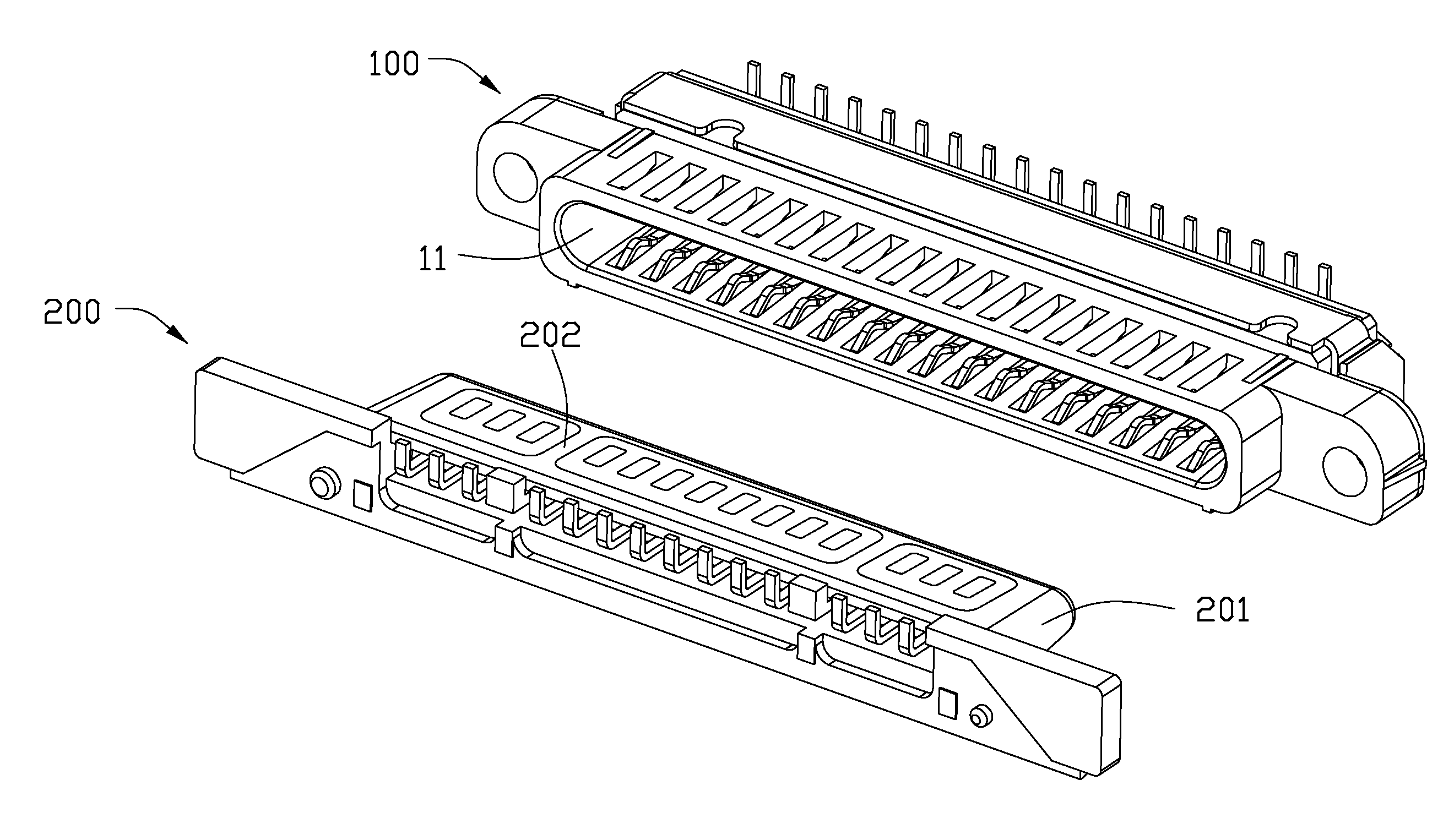
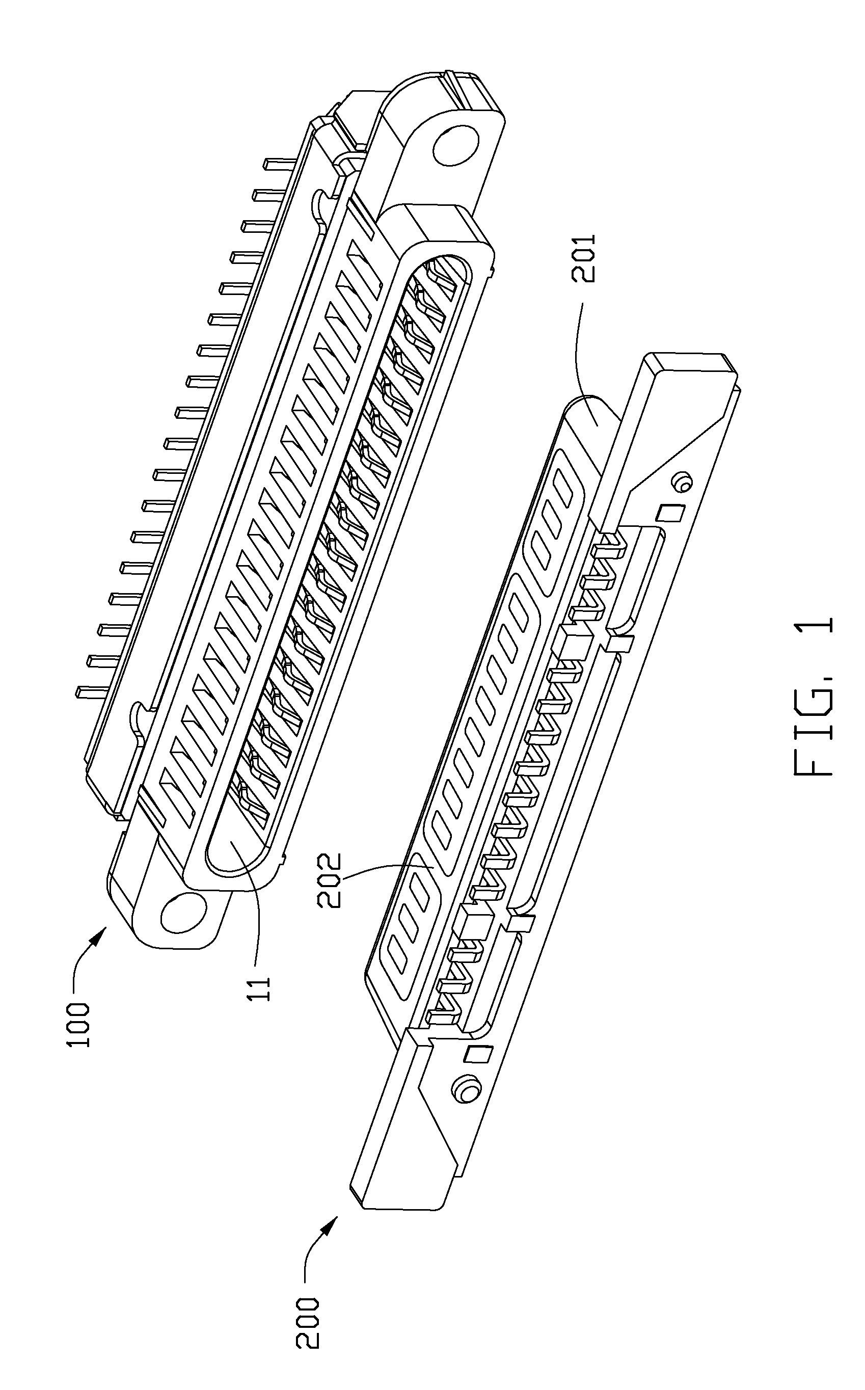
[0016]Referring to FIG. 1, the present invention provides an electrical connector assembly with good anti-electromagnetic interference ability. The electrical connector assembly comprises a first electrical connector (or electrical connector) 100 and a second electrical connector (or complementary connector) 200 mated with each other. The first electrical connector 100 defines a lengthwise mating cavity 11 extending along a longitudinal direction, and the second electrical connector 200 has a mating portion 202 formed as part of a metal shell 201 intended to be inserted into the mating cavity 11. The mating portion 202 is a conductive configuration.

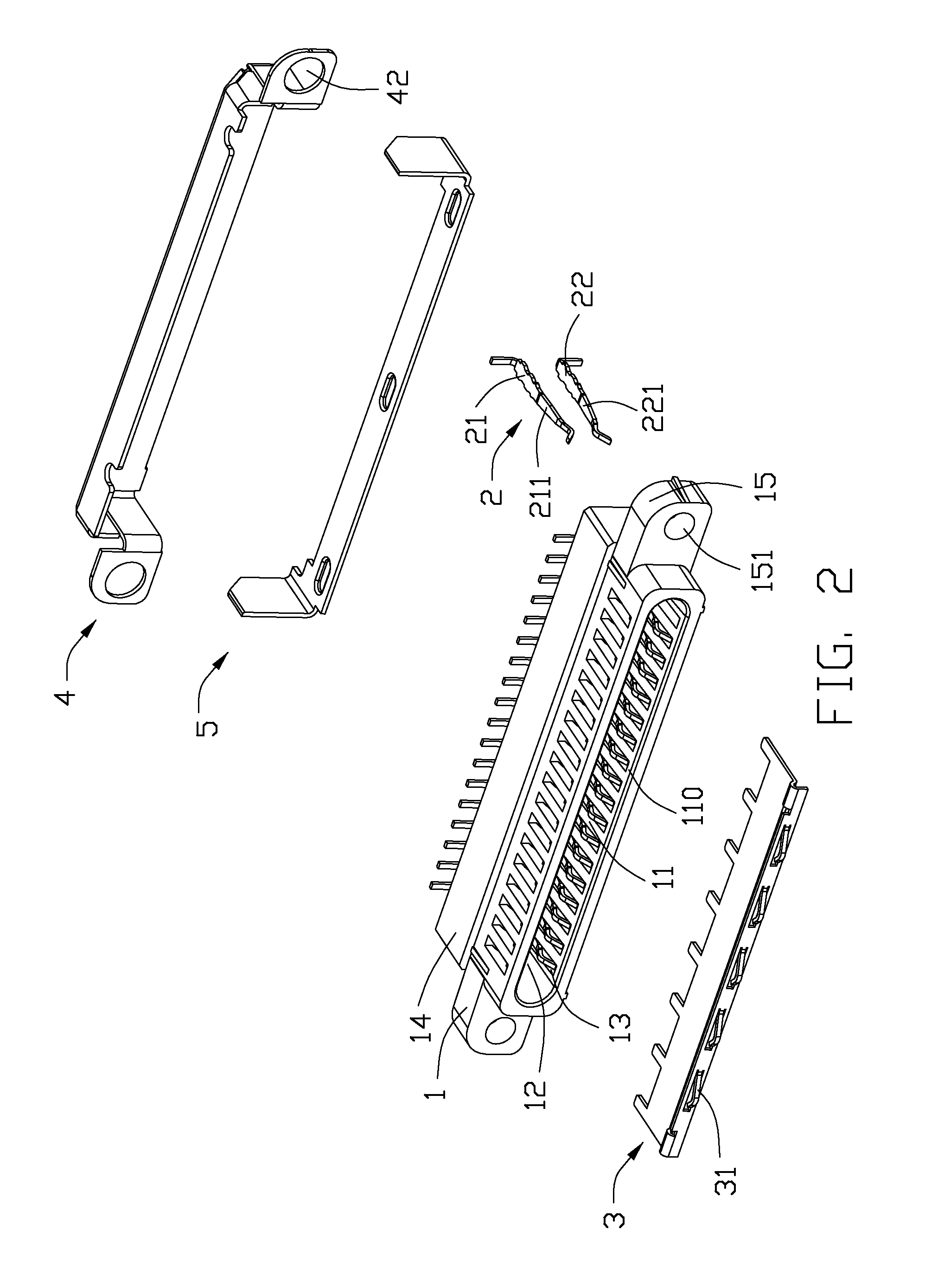
[0017]Referring to FIG. 2, the first electrical connector 100 comprises an insulative housing 1, a plurality of conductive terminals 2 installed in the insulative housing 1 and a grounding plate 3 secured in the insulative housing 1. The insula...


PUM


Abstract

An electrical connector assembly includes a first electrical connector and a second electrical connector mated with each other. The first electrical connector includes an insulative housing, a plurality of conductive terminals and a grounding plate. The insulative housing extending along a longitudinal direction includes a base portion and a plurality of side walls extending forwardly from the base portion and forming a mating cavity. The insulative housing defines a plurality of first passageways and second passageways separately formed in two opposite side walls thereof communicating with the mating cavity. The conductive terminals include a plurality of first terminals and second terminals received in the corresponding first and second passageways. Each of the first and second terminals has a contact portion extending into the mating cavity. The grounding plate is disposed between the first and second terminals and defines at least one pressing portion located in the mating cavity.

Description

BACKGROUND OF THE INVENTION[0001]1. Field of the Invention[0002]The present invention generally relates to an electrical connector, and more particularly to an electrical connector with a grounding plate secured therein.[0003]2. Description of Related Art[0004]TW patent No. M367498 discloses an electrical connector comprising an insulator, a plurality of ESATA terminals, a plurality of USB terminals and a grounding plate. The insulator defines a receptacle space running through the front face thereof and a mating tongue extending into the receptacle space along a first orientation. The mating tongue defines a first face and a second face opposite to the first surface. Each of the ESATA terminals has a contact section disposed in the first face of the mating tongue, and each of the USB terminals has a contact section disposed in the second face of the mating tongue. The grounding plate is disposed between the first and second faces of the mating tongue, and is spaced with the ESATA a...

Claims


Application Information

Patent Timeline
Patent Type & Authority Applications(United States)
IPC IPC(8): H01R13/6585H01R13/46
CPCH01R13/46H01R13/6585
Inventor LI, XIN-XINQIAN, QIULI, CHUN-SHENGZHU, JIAN-KUANG
Owner HON HAI PRECISION IND CO LTD
Why Eureka
Try Eureka