Electrode module for LED lamp

Inactive Publication Date: 2015-03-19
TRUE STAR
View PDF7 Cites 0 Cited by
  • Summary
  • Abstract
  • Description
  • Claims
  • Application Information

AI Technical Summary

Benefits of technology

[0005]As described above, the electrode module for the LED module according to the present invention maximizes the surface area of the electrode portion on which the LED device is mounted, thus minimizing thermal resistance and maximizing the flow of electrons in the lead wire, and maximally copes with surface resistance on the surface of the electrode in the LED, thus minimizing a voltage drop.
[0006]In addition, the electrode module of this invention can ensure the massive heat transfer passage and electricity flow passage which are minimized in terms of resistance due to the maximized electrode surface area, and allows the thermal equilibrium between the LED and the electrode to be rapidly reached as the surface area of the electrode is increased. Thus, it is possible to solve the problem where the temperature of the LED active layer abr

Problems solved by technology

Thus, the rapid removal of heat generated from the LED can increase the generation of photons.
That is, a quantity of heat exceeding a quantity that is required to appropriately activate the electrons reduces the generation of the photons, and an excessive quantity of current resulting from the heat lowers a binding force between atomic structures, with the result that the LED may be undesirably destroyed.
The problem relating to such heat generation occurs when the LED light source of high luminance and high electric power to be used as an illumination is manufactured.
However, the

Method used


Image

  • Electrode module for LED lamp
  • Electrode module for LED lamp
  • Electrode module for LED lamp

Examples


Example

BEST MODE

[0022]Hereinafter, the present invention will be described in detail with reference to the accompanying drawings. Like reference numerals designate like elements throughout the specification. In the following description, if it is decided that the detailed description of known function or configuration related to the invention makes the subject matter of the invention unclear, the detailed description is omitted. Exemplary embodiments of the present invention will be provided to make the present invention be more completely understood by those skilled in the art. Thus, the shape and size of components may not be illustrated to scale in the drawings but may be exaggerated for clarity.

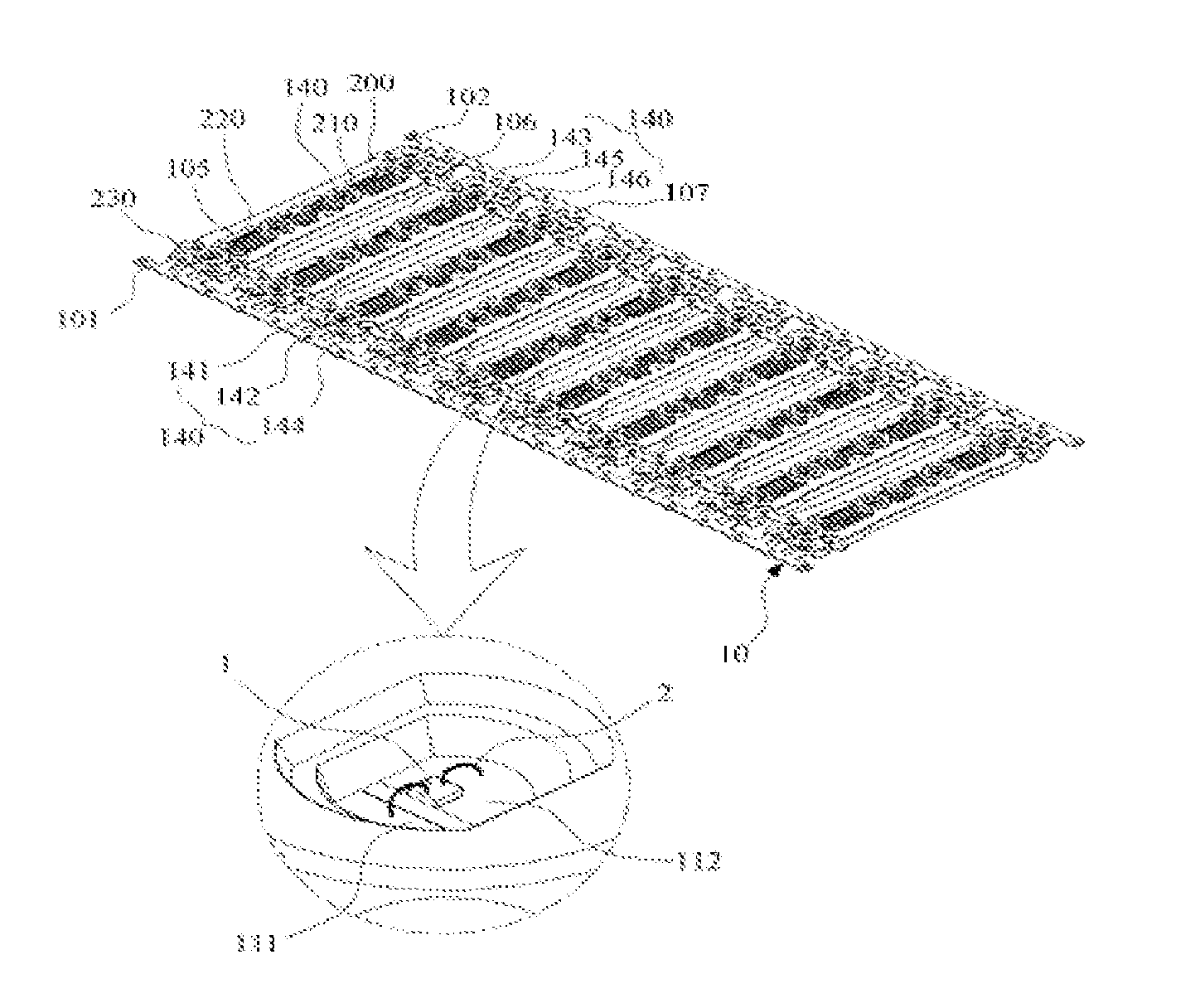
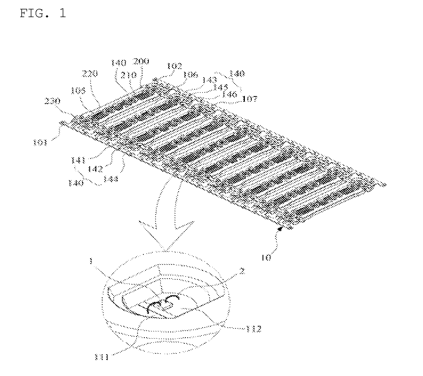
[0023]FIG. 1 is a perspective view showing a state where an original electrode plate is coupled with a frame according to an embodiment of the present invention. The electrode module for the LED lamp according to the present invention includes a frame 200 which is made of a nonconductive materia...


PUM


Abstract

There is provided an electrode module for an LED lamp. The electrode module is provided by cutting an original electrode plate in a predetermined shape, the original electrode plate including a nonconductive frame having a mounting hole for accommodating an LED device, and a conductive electrode pattern integrally coupled with the frame and supplying power to the LED device. The electrode pattern has unit bodies formed repeatedly, and each unit body includes first and second parallel lines arranged on both sides, a body portion interposed between the first and second parallel lines, and upper and lower lines arranged at the upper and lower portions of the body portion and connected with the body portion through a vertical disconnectable portion. Both sides of the upper and lower lines connected to the body portions, which are adjacent to each other, are connected with each other through first and second serial lines.

Description

TECHNICAL FIELD[0001]The present invention relates, in general, to an electrode module for an LED lamp and, more particularly, to an electrode module for an LED lamp, which is capable of using electrode patterns of various structures by cutting an original electrode plate which has unit bodies formed repeatedly thereon in accordance with a use thereof.BACKGROUND ART[0002]Generally, an LED is a kind of diode. When a voltage is forwardly applied to the LED, electrons are transferred by electromagnetic induction. At this time, the electrons generate light energy and thermal energy, which are in inverse proportion to each other. Thus, the rapid removal of heat generated from the LED can increase the generation of photons. When a light source of the LED maintains an active temperature of about 25 to 55° C., light output and light efficiency can be maximized. Further, it is possible to maintain the durability of the LED. That is, a quantity of heat exceeding a quantity that is required to...

Claims


Application Information

Patent Timeline
IPC IPC(8): H01L33/64H01L33/38
CPCH01L33/387H01L33/644F21K9/20F21V23/002F21V23/06F21Y2101/00H01L24/97H01L2224/48091H01L2224/48247H01L2224/48257H01L2224/73265H01L25/0753H01L33/62H01L33/642H01L33/647H01L2933/0066H01L2924/12041F21Y2105/10F21Y2103/10F21Y2115/10H01L2924/00014H01L2924/00F21S2/005H05K1/00F21K9/00
Inventor CHOI, WONE-HEE
Owner TRUE STAR
Why Eureka
Try Eureka