Head unit and image recording device

a recording device and head unit technology, applied in the direction of printing, inking apparatus, other printing apparatus, etc., can solve the problems of poor maintenance efficiency of head and flow path member, inability to inability to support the electrical circuit substrate on the support substrate together with these become obstacles, so as to facilitate maintenance and efficiently perform maintenance work, the effect of efficient maintenance work

Active Publication Date: 2015-03-19
SEIKO EPSON CORP
View PDF2 Cites 17 Cited by
  • Summary
  • Abstract
  • Description
  • Claims
  • Application Information

AI Technical Summary

Benefits of technology

[0015]It is also possible to have the liquid be cured by light irradiation. In other words, in this case, it is possible that liquid cured due to leaked light or the like will adhere to the head and the flow path member. In response to this, with the invention, it is possible to easily perform maintenance on the head and the flow path member, making it possible to suitably handle the problem of liquid becoming adhered.
[0016]It is also possible to constitute the head unit such that in a state where the first holding member and the second holding member are engaged, the first holding member at least partially hides the flow path member. In other words, with that constitution, in a state with the second holding member and the first holding member engaged, it is possible to have a case for which the flow path member is hidden by the first holding member, so that maintenance on the flow path member cannot be performed efficiently. In response to this, with the invention, by separating the first holding member and the second holding member, it is possible to pull away the flow path member from the first holding member. As a result, it is possible to efficiently perform maintenance work on the flow path member without interference by the first holding member.

Problems solved by technology

However, with Unexamined Patent Publication No. 2007-223196, during maintenance of the head and the flow path member, the electrical circuit substrate supported on the support substrate together with these becomes an obstacle.
Because of that, the head and flow path member maintenance work efficiency was not good.
In other words, with that constitution, in a state with the second holding member and the first holding member engaged, it is possible to have a case for which the flow path member is hidden by the first holding member, so that maintenance on the flow path member cannot be performed efficiently.

Method used


Image

  • Head unit and image recording device
  • Head unit and image recording device
  • Head unit and image recording device

Examples


Embodiment Construction

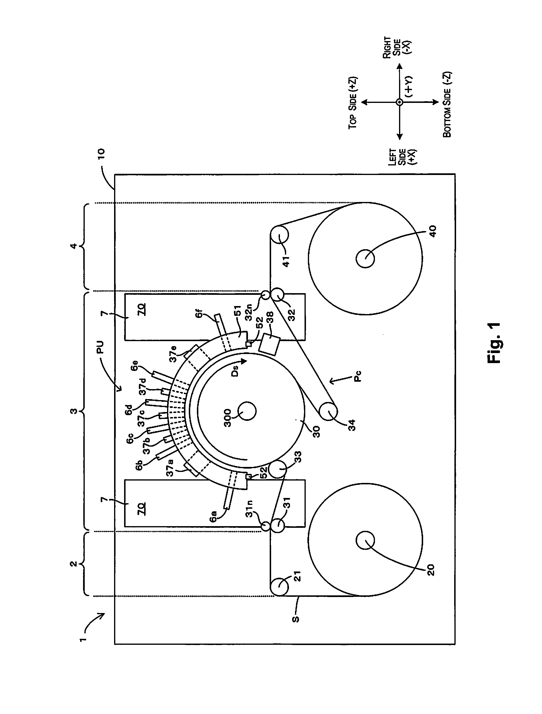
[0023]FIG. 1 is a front view showing a typical example of the schematic constitution of a printer to which the present invention can be applied. With FIG. 1 and the drawings hereafter as necessary, to clarify the arrangement relationship of each of the parts of the device, an XYZ orthogonal coordinate system is displayed corresponding to the left and right direction X, front and back direction Y, and vertical direction Z of a printer 1.

[0024]As shown in FIG. 1, with the printer 1, one sheet S (web) for which both ends are wound in roll form on a feed shaft 20 and a take-up shaft 40 is stretched along a conveyance path Pc, and the sheet S undergoes image recording while being conveyed in a conveyance direction Ds facing from the feed shaft 20 to the take-up shaft 40. The sheet S types are roughly divided into paper and film. To list specific examples, for paper, there is high quality paper, cast coated paper, art paper, coated paper and the like, and for film, there is synthetic pape...


PUM


Abstract

An electrical circuit substrate, a first holding member holding the electrical circuit substrate, a head configured to discharge liquid, a flow path member having a flow path in which flows the liquid supplied to the head, and a second holding member holding the head and the flow path member are provided. The first holding member and the second holding member are detachably attached with each other.

Description

CROSS-REFERENCE TO RELATED APPLICATIONS[0001]This application claims priority to Japanese Patent Application No. 2013-193896 filed on Sep. 19, 2013. The entire disclosure of Japanese Patent Application No. 2013-193896 is hereby incorporated herein by reference.BACKGROUND[0002]1. Technical Field[0003]The present invention relates to a head unit equipped with a head, a flow path member, and an electrical circuit substrate, and to an image recording device equipped with that head unit.[0004]2. Related Art[0005]With Unexamined Patent Publication No. 2007-223196, noted is a constitution with which ink is supplied to a head using an ink flow path forming member for which the ink flow path is formed on the interior. The ink flow path forming member and the head are supported on a common support substrate. Furthermore, this support substrate also supports an electrical circuit substrate of an ICB substrate and a relay substrate. In other words, with Unexamined Patent Publication No. 2007-22...

Claims


Application Information

Patent Timeline
Patent Type & Authority Applications(United States)
IPC IPC(8): B41J2/14
CPCB41J2002/14491B41J2/14B41J2/14072B41J29/377B41J2202/12B41J2202/19B41J2202/20B41J2/18B41J2/2114B41J2/175
Inventor WANIBE, AKIHISASHIMAZAKI, JUN
Owner SEIKO EPSON CORP
Why Eureka
Try Eureka