Illuminated Endoscopic Pedicle Probe With Electromyographic Monitoring
- Summary
- Abstract
- Description
- Claims
- Application Information
AI Technical Summary
Benefits of technology
Problems solved by technology
Method used
Image
Examples
first embodiment
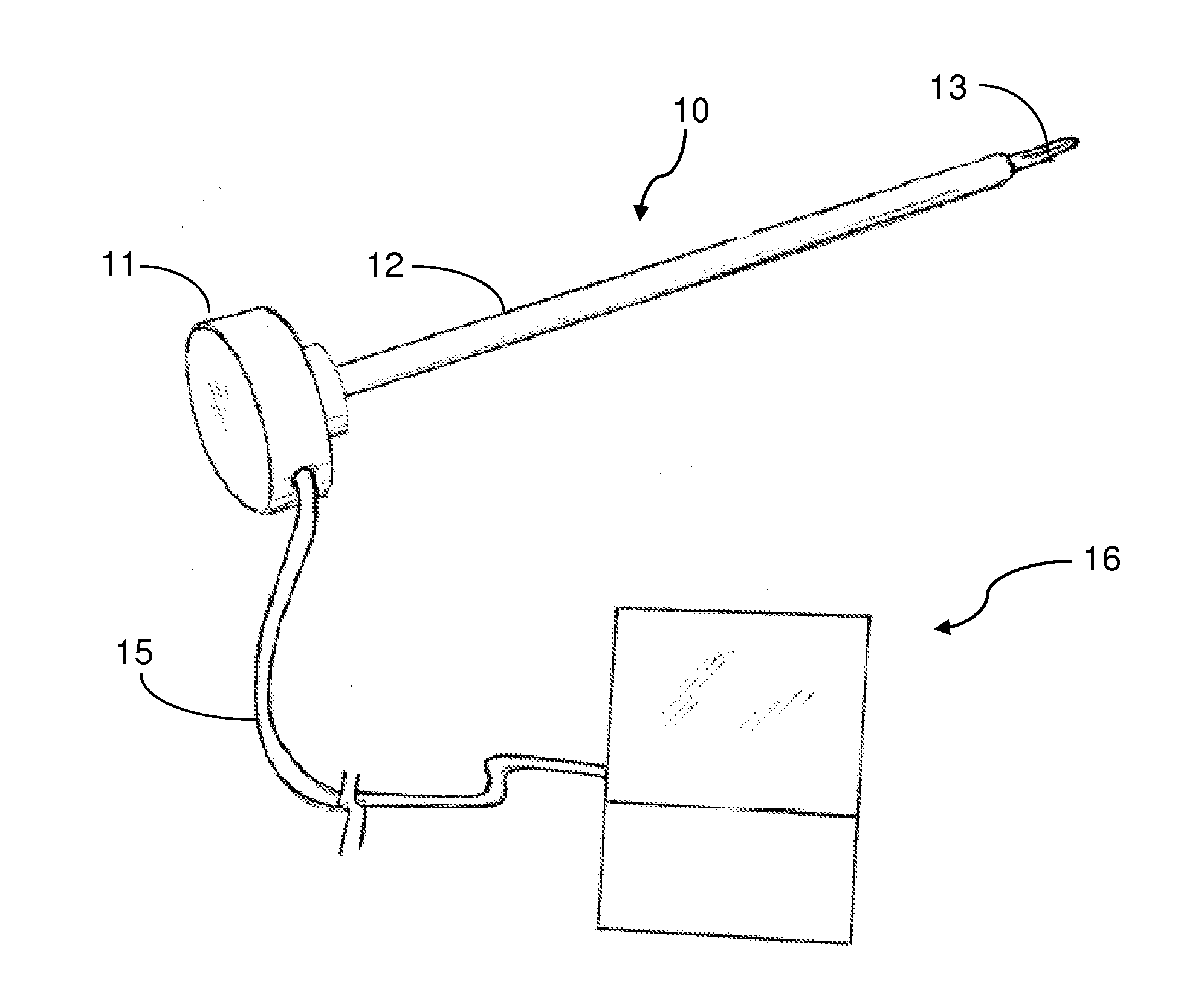
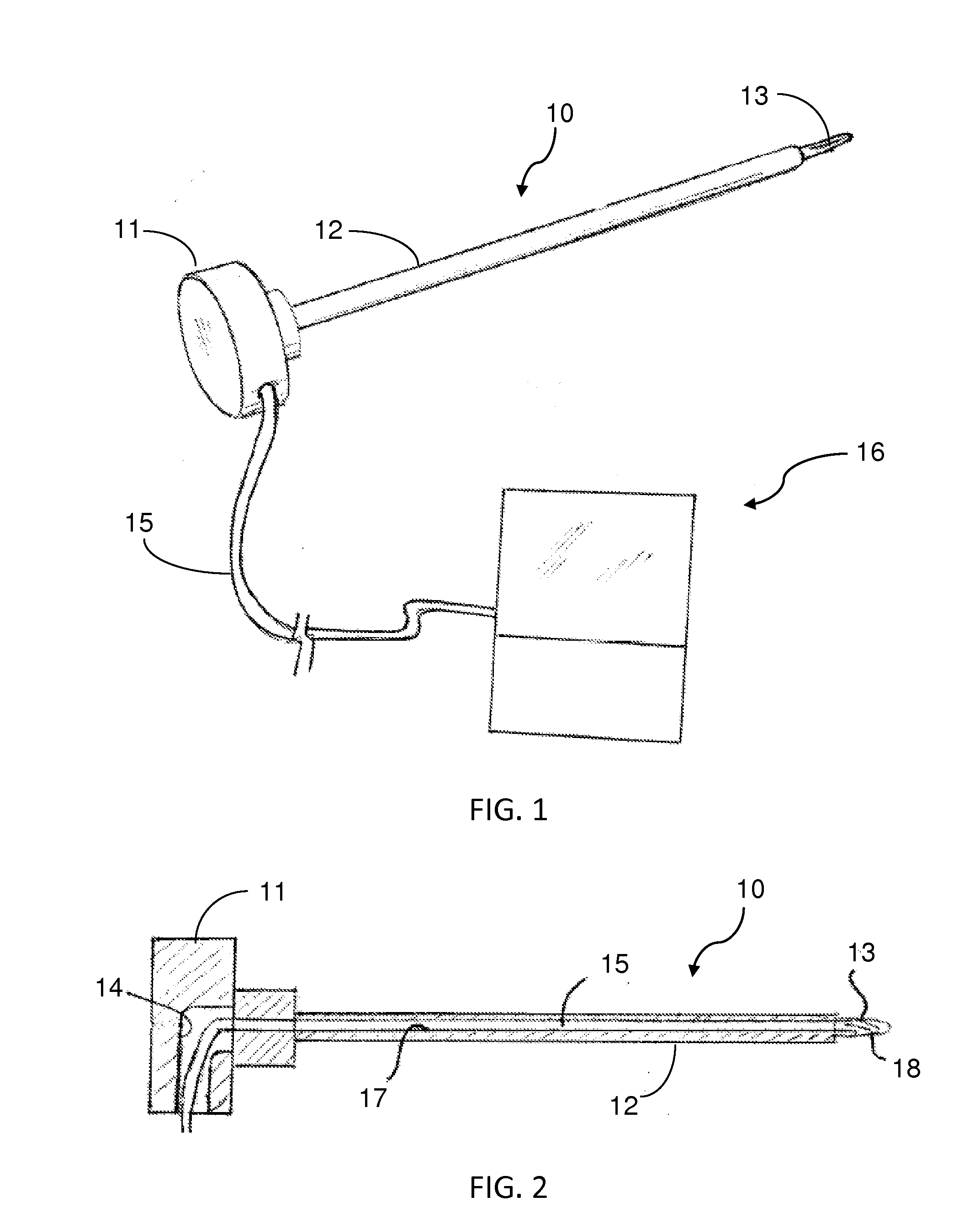
[0056]Referring more specifically to the drawings, a pedicle probe according to the invention is depicted at 10 in FIG. 2. The probe has a disc-shaped head 11 on its proximal end that is about two inches in diameter, and a metal shaft 12 projecting from the center of one side thereof. A reduced diameter tip 13 on the distal end of the shaft is configured to act as a reamer, i.e., it may have a fluted configuration as found on drill bits. In use, a surgeon places the disc-shaped head 11 in the palm of his or her hand, with the shaft extending forwardly. The tip is then pushed against the pedicle while the probe is being rotated back and forth about the longitudinal axis of the shaft to form a hole in the pedicle for reception of a pedicle screw. See, for example, FIGS. 12-19.
[0057]In the embodiment shown in FIGS. 1 and 2, the disc-shaped head 11 of the probe 10 has an opening 14 formed in it for receipt of an endoscope 15 with integrated illumination means, such as the Medigus LEDpro...
second embodiment
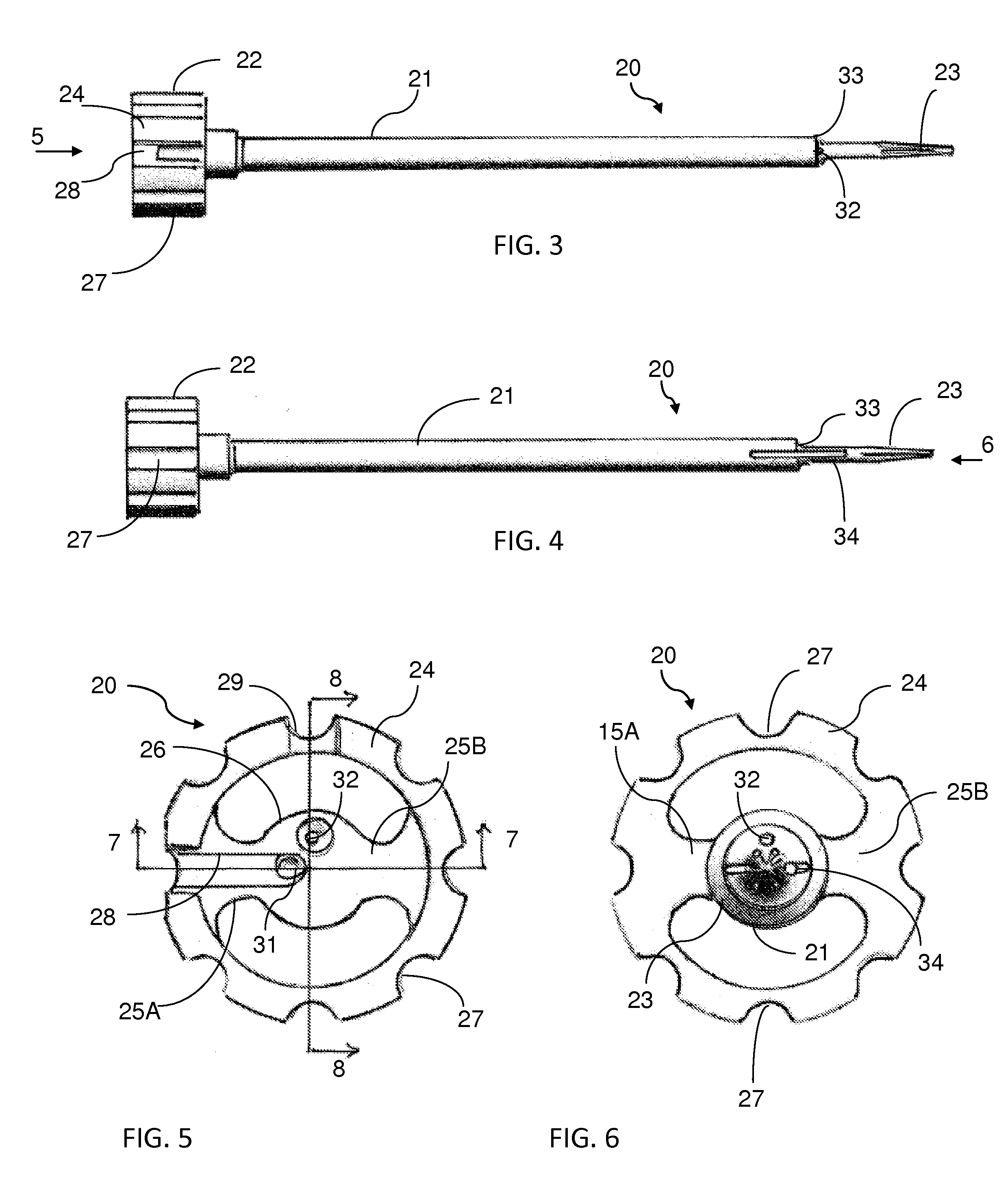
[0059]endoscopic pedicle probe according to the invention is indicated generally at 20 in FIGS. 3-11. Although not shown, an endoscope with integrated illumination means as described in connection with the FIG. 1 embodiment, i.e. the Medigus LEDprobe, may also be used in this form of the invention. This form differs from that shown in FIG. 1 in that the tip 23 can be configured to position the camera 25 for providing a 90° view or a 45° forward view or a 0° view straight ahead. Thus, by selection of an appropriate probe, or by appropriate manipulation of a probe, the surgeon can obtain a direct visual indication of the exact position of the probe in the pedicle and of the pedicle itself and surrounding structure. As depicted in these figures, the camera is placed rearwardly of the distal point of the end to protect it when the probe is pressed against and pushed through hard bony tissue. An obturator, not shown, may be provided to close the opening through the side of the tip and pr...
third embodiment
[0065]probe according to the invention is shown in FIGS. 20 and 21. In this embodiment, two endoscopes 40 and 41 are provided in the probe. One of the endoscopes 41 has its camera 25 positioned at the distal end of the tip 43 in a zero degree forwardly facing orientation. The other endoscope 40 has its camera 25 positioned at the distal end 44 of the probe shaft 45 and oriented in a camera window slot 46 to provide about a 70° view looking at the side of the pedicle wall. The endoscopes 40 and 41 preferably have an illuminating means integrated with them, as in the Medigus LEDprobe discussed above, and / or a separate light 47 may be provided. A saline rinse port 48 also preferably is provided at the distal end of the probe shaft to rinse away debris during use of the probe to keep the field of vision clear.
[0066]A fourth embodiment 50 of pedicle probe according to the invention is shown in FIGS. 22-25. In this form of the invention, rather than extend bores longitudinally through the...
PUM
 Abstract
Description
Claims
Application Information
 - R&D
- Intellectual Property
- Life Sciences
- Materials
- Tech Scout
- Unparalleled Data Quality
- Higher Quality Content
- 60% Fewer Hallucinations
Browse by: Latest US Patents, China's latest patents, Technical Efficacy Thesaurus, Application Domain, Technology Topic, Popular Technical Reports.
© 2025 PatSnap. All rights reserved.Legal|Privacy policy|Modern Slavery Act Transparency Statement|Sitemap|About US| Contact US: help@patsnap.com


