Illuminated Endoscopic Pedicle Probe With Replaceable Tip

a pedicle probe and replaceable technology, applied in the field of surgical instruments, can solve the problems of dural or neural injury, dural or medial penetration of the pedicle cortex, no direct confirmation, etc., and achieve the effect of direct and accurate determination, no additional costs or equipment, and avoiding parallax

Inactive Publication Date: 2014-05-22
OPTICAL SPINE LLC
View PDF8 Cites 17 Cited by
  • Summary
  • Abstract
  • Description
  • Claims
  • Application Information

AI Technical Summary

Benefits of technology

[0022]The endoscopic pedicle probe of the invention puts the surgeon “in the pedicle” with the use of endoscopy. The positioning of the probe can be directly and accurately determined during surgery, and there is no question as to whether the screw will be too medial, lateral, cranial, caudal, or deep. The surgeon will know if the wall of the pedicle has been breached, and to what extent. He or she can then decide to use the planned trajectory even if there is a small breach of the pedicle wall. The probe of the invention provides the surgeon with knowledge of how much of an intrusion exists, and he or she can ascertain if critical structures will be in danger from screw placement. The surgeon can also avoid parallax that may cause errors when using fluoroscopic guidance.
[0023]Further, a probe must be used in any event to perform spinal fusions, and the probe of the invention will not represent an additional instrument needed for pedicle screw placement. Accordingly, there will be no additional costs or equipment needed to perform the standard spinal fusion.

Problems solved by technology

These conventional modalities require a steep learning curve, and improper or inaccurate manipulation of the probe and placement of the pedicle screw can result in caudal or medial penetration of the pedicle cortex and dural or neural injury.
With conventional pedicle probes there is no direct way to confirm that the hole was made within the pedicle and that the screw will be placed completely inside the pedicle.
Surrounding structures can be injured if a portion of the screw is placed outside of the pedicle.
There can be nerve root injury, epidural vessel injury, or spinal fluid leakage caused by a misplaced screw.
Currently, there are no pedicle probes having any means to illuminate the pedicle.
Additionally, the distal tip of the probe can become worn or damaged during use, rendering the whole instrument unusable or reducing its usefulness.
Further, body fluids and debris can accumulate at the area being treated, blocking or degrading the view provided by the endoscope.

Method used


Image

  • Illuminated Endoscopic Pedicle Probe With Replaceable Tip
  • Illuminated Endoscopic Pedicle Probe With Replaceable Tip
  • Illuminated Endoscopic Pedicle Probe With Replaceable Tip

Examples


Embodiment Construction

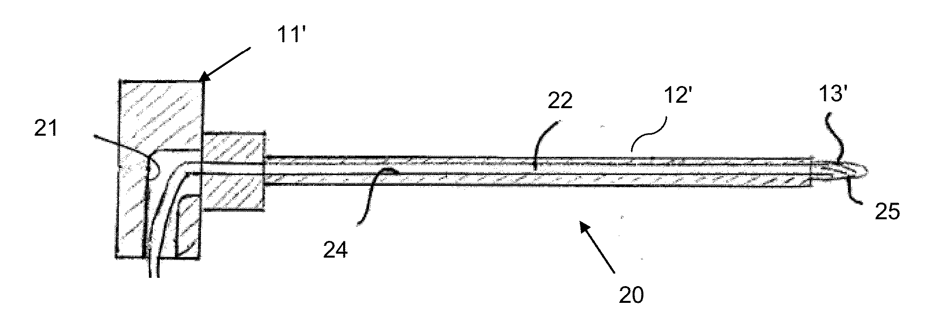
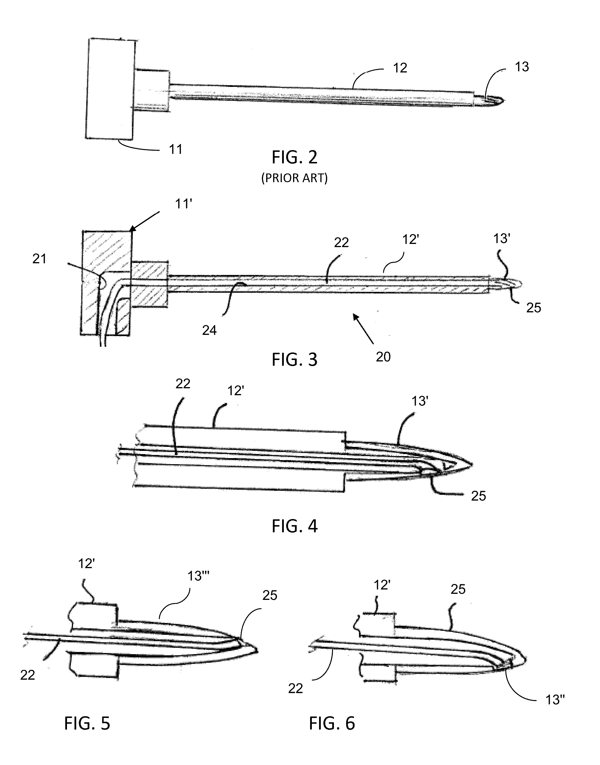
[0059]Referring more specifically to the drawings, a conventional Fox pedicle probe is depicted at 10 in FIG. 2. The probe has a disc-shaped head 11 on its proximal end that is about two inches in diameter, and a solid metal shaft 12 projecting from the center of one side thereof. A reduced diameter tip 13 on the distal end of the shaft is configured to act as a reamer, i.e., it may have a fluted configuration as found on drill bits. In use, a surgeon places the disc-shaped head 11 in the palm of his or her hand, with the shaft extending forwardly. The tip is then pushed against the pedicle while the probe is being rotated back and forth about the longitudinal axis of the shaft to form a hole in the pedicle for reception of a pedicle screw. See, for example, FIGS. 9-14.

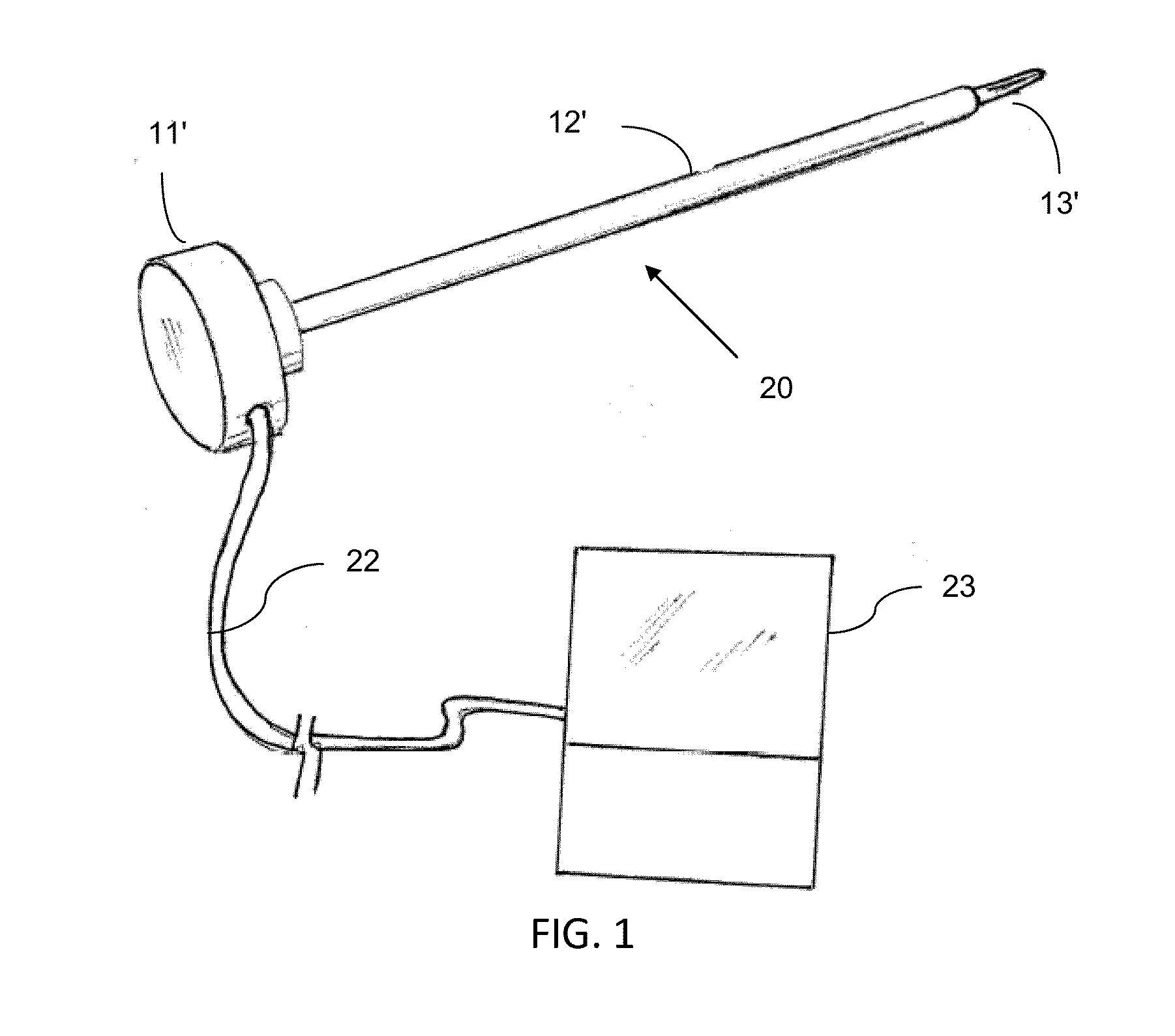
[0060]In the specific embodiment illustrated and described herein, the pedicle probe 20 of the invention, as shown in FIGS. 1 and 3-15, is based on the Fox pedicle probe of FIG. 2. However, it should be understood tha...


PUM


Abstract

An endoscopic pedicle probe for use during spinal surgery to form a hole in a pedicle for reception of a pedicle screw has an enlarged proximal end for cooperation with the hand of the surgeon and an elongate shaft terminating in a distal tip that may be pushed through the pedicle to form the hole. The tip may be detachable for replacement. An endoscope extends through the shaft and is connected with a monitor to enable the surgeon to visually observe the area being treated. In a preferred form a light means extends through the shaft to illuminate the area being treated, and in a further preferred form a conduit extends through the shaft to convey a fluid to flush the area being treated. In a further embodiment, two endoscopes are associated with the probe.

Description

[0001]This application claims the benefit of U.S. provisional patent application Ser. No. 61 / 647,747, filed May 16, 2012, incorporated in full herein by reference.TECHNICAL FIELD[0002]This invention relates generally to surgical instruments. More specifically, the invention relates to a pedicle probe for use in forming holes in a vertebral pedicle in preparation for pedicle screw insertion. According to one feature of the invention the probe incorporates at least one endoscope to enable the surgeon to see the area being treated. According to another feature the probe has a light to illuminate the area being treated, and according to a further feature the probe has a replaceable tip on its distal end. According to a still further feature the probe has a channel for directing a flushing fluid to the area being treated to maintain a clear field of vision for the endoscopic camera. The probe of the invention may have any one or any combination of these features.BACKGROUND ART[0003]It is...

Claims


Application Information

Patent Timeline
Patent Type & Authority Applications(United States)
IPC IPC(8): A61B17/16A61B1/04A61B1/00A61B17/00A61B1/015A61B19/00A61B1/06
CPCA61B17/1604A61B1/00045A61B1/00135A61B1/015A61B19/5244A61B1/06A61B17/00234A61B17/1655A61B1/04A61B17/1615A61B17/1671A61B1/3135A61B17/7074A61B1/126A61B17/3472A61B17/88A61B1/317
Inventor JACKSON, III, AVERY M.
Owner OPTICAL SPINE LLC
Why Eureka
Try Eureka