Custom Coffered Surface Layout, Fabrication, and Installation Methods and Processes

Inactive Publication Date: 2015-03-26
TILTON JASON
View PDF15 Cites 0 Cited by
  • Summary
  • Abstract
  • Description
  • Claims
  • Application Information

AI Technical Summary

Benefits of technology

The present invention is a custom coffered ceiling system that includes a panel and beam wall boards attached perpendicular to a first side of the panel and forming the side walls for a pattern of intersecting, non-structural hollow box beams. The panel extends past the beam wall boards to create a fastening flange or point by which one or more modules are secured to a substrate. The system has several primary components that are prefabricated and preassembled to create individual coffer modules that can be easily installed on an imperfect surface and can achieve a perfectly level, straight, or flat plane across the installation. The prefabrication and preassembly methods and processes of the system allow it to be installed faster and with less labor and materials than conventional custom onsite installation, which results in significant cost savings and improved safety and cleanliness conditions.

Problems solved by technology

Furthermore, the present system significantly reduces the labor, time, materials, and equipment required to complete the installation process.

Method used


Image

  • Custom Coffered Surface Layout, Fabrication, and Installation Methods and Processes
  • Custom Coffered Surface Layout, Fabrication, and Installation Methods and Processes
  • Custom Coffered Surface Layout, Fabrication, and Installation Methods and Processes

Examples


Embodiment Construction

[0078]In the following, the description, as well as parts thereof, will be described, and by way of example, the same or similar elements will have the same or similar reference signs. For these embodiments, arches, curves, angles are described. An arch has to be understood as also meaning at least, but not limited to, components which have a radius that is perpendicular to the ceiling / surface panel, while a curve has to be understood as also meaning at least, but not limited to, components which have a radius that is parallel to the ceiling / surface panel and angle has to be understood as also meaning at least, but not limited to, components which are positioned in a manner other than parallel or perpendicular in relation to one another.

[0079]A. Description of the Present System

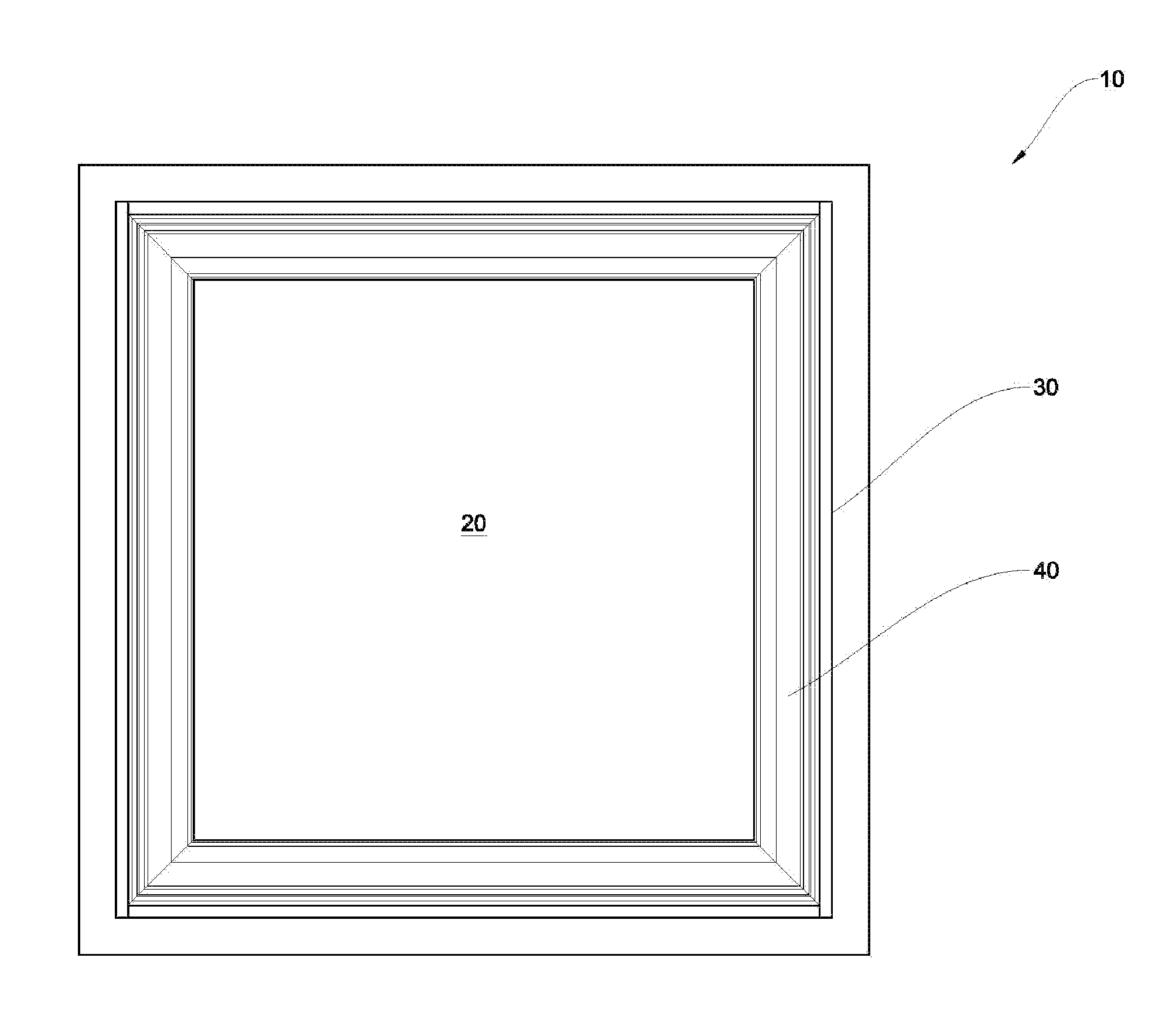
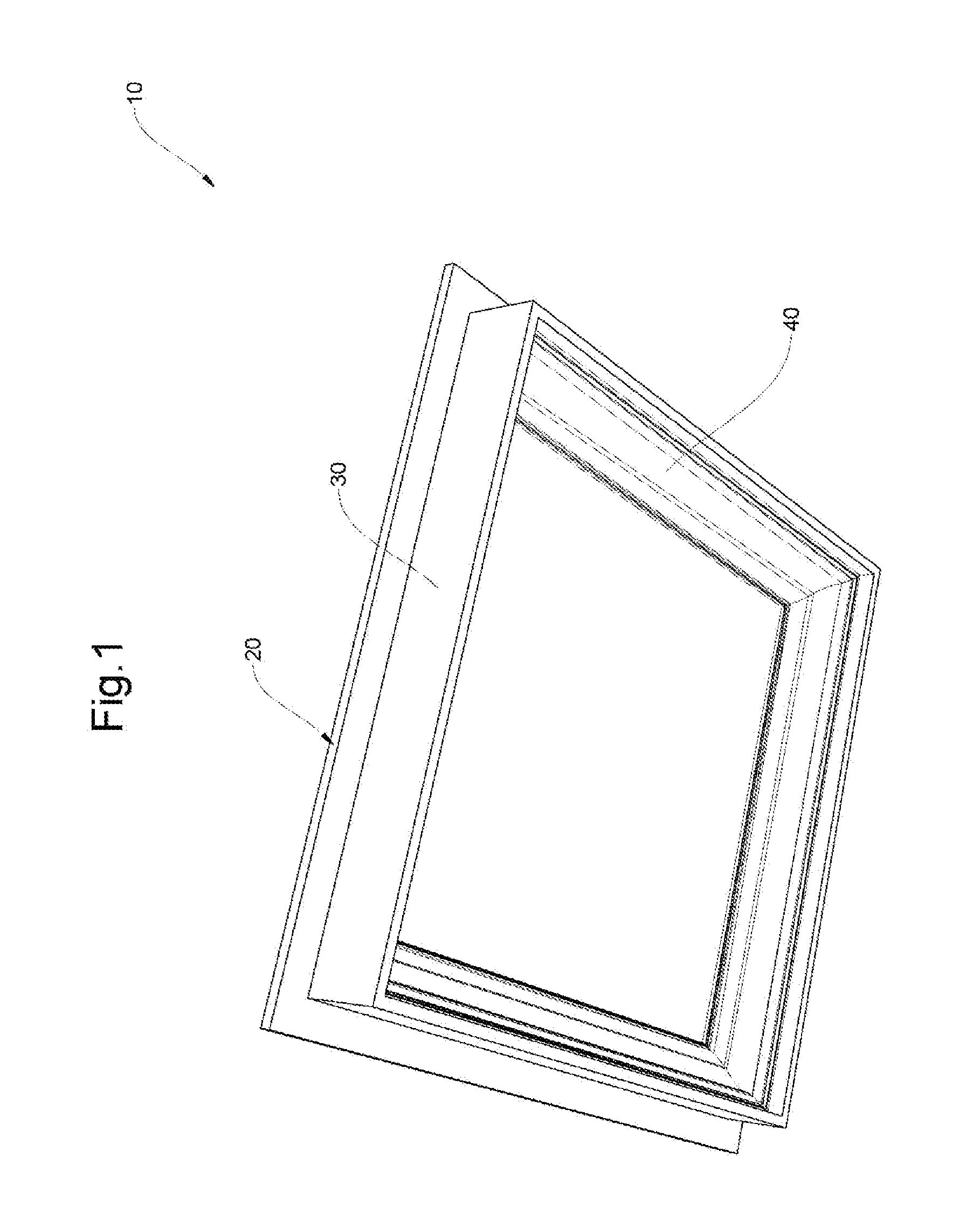
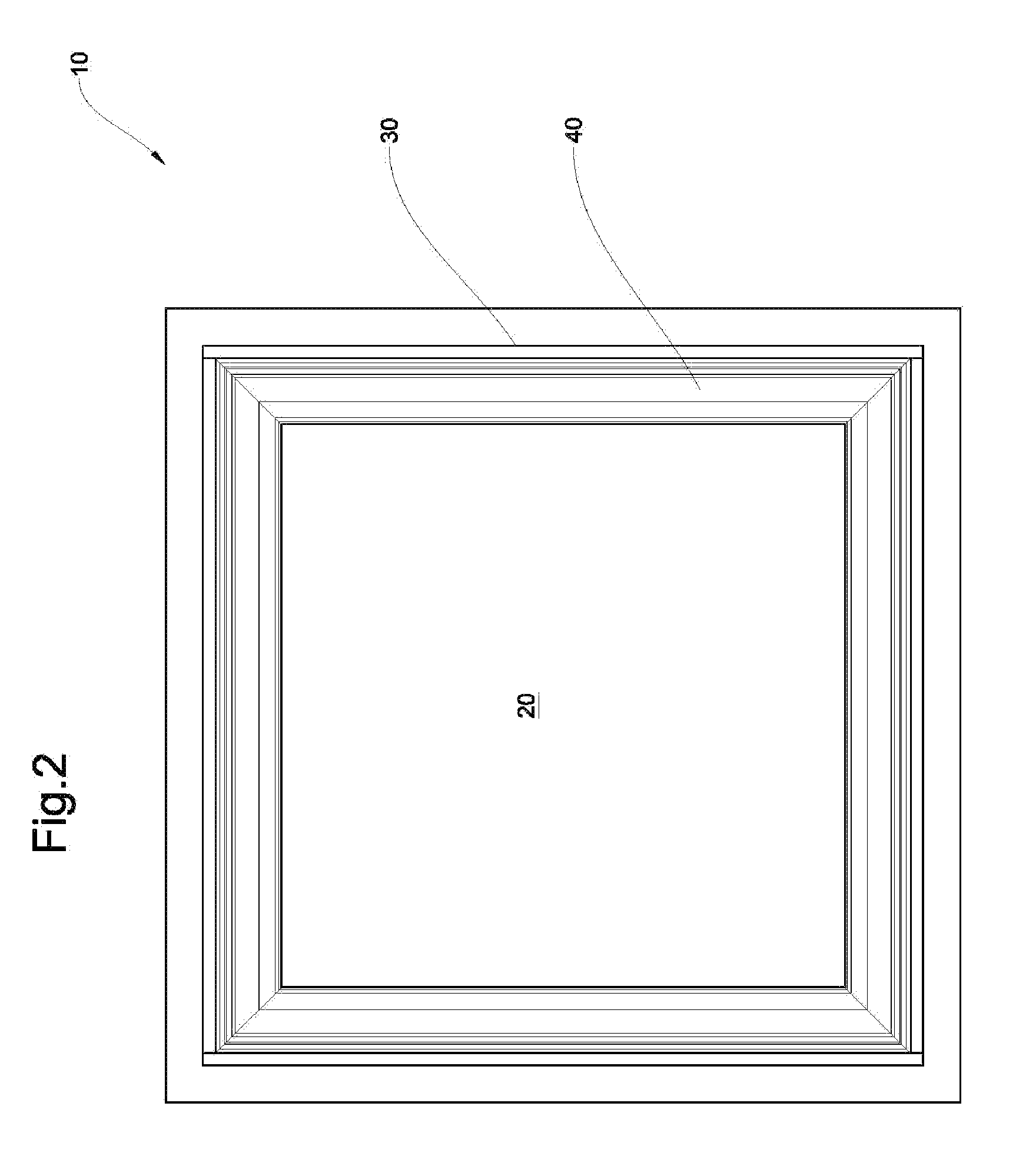
[0080]In FIGS. 1, 2 and 3, the single coffer module of the present system 10 consists of a ceiling / surface panel 20, a beam wall board 30 and a beam molding 40.

[0081]As illustrated in FIGS. 4 and 5, an entire...


PUM


Abstract

A coffer includes a panel; beam wall boards attached perpendicular to a first side of the panel and extending away from the panel and forming the side walls for a pattern of intersecting, non-structural hollow box beams, wherein the panel extends past the beam wall boards to create a fastening flange or point by which one or more modules are secured to a substrate; and a beam wall molding cut to size and custom-fitted to the beam wall boards and a panel after the beam wall boards have been attached to the panel, wherein the beam wall molding connects surfaces between the beam wall boards and the panel without covering the beam wall board edges and wherein the panel directly terminates into a perpendicular wall or surface or into the substrate and wherein the modules and resulting hollow box beams include polygonal and curved shapes and wherein the beam wall moldings follow the exact shape of the beam wall boards to eliminate spaces between the beam wall moldings and the beam wall board that would require filling by an additional board, part or component.

Description

[0001]This application is a continuation in part application of Ser. No. 13783177 filed Mar. 1, 2013, which is a divisional of Ser. No. 13269929 filed Oct. 10, 2011, the contents of which are incorporated by reference.BACKGROUND OF THE INVENTION[0002]The present system relates generally to a custom fitted and permanently applied decorative coffered surface.DESCRIPTION OF RELATED ART[0003]The intersecting grid of structural beams that made up the very first coffered ceilings were designed to help support heavy roof loads, but consequently they also added to the ceiling's architectural and visual appeal. Today's coffered ceilings are primarily installed as an aesthetic element and use a grid of intersecting, non-structural, typically hollow, box beams to replicate the desirable look and feel of their structural predecessors. The main purpose of the modern day coffered ceiling is to add decoration and appeal to an otherwise plain and unappealing surface. Likewise, a coffered detail of ...

Claims


Application Information

Patent Timeline
IPC IPC(8): E04C2/40E04F13/07
CPCE04C2/40E04F2203/00E04C2002/005E04F13/07E04F19/0436E04B9/0428E04F13/00E04F19/00
Inventor TILTON, JASON
Owner TILTON JASON
Why Eureka
Try Eureka