Subterranean Solids Separator

a separator and subterranean technology, applied in fluid removal, earthwork drilling and mining, borehole/well accessories, etc., can solve the problem of limited debris separation capability, and achieve the effect of narrow width, less turbulence, and greater radius turn

Active Publication Date: 2015-03-26
BAKER HUGHES INC
View PDF1 Cites 4 Cited by
  • Summary
  • Abstract
  • Description
  • Claims
  • Application Information

AI Technical Summary

Benefits of technology

The invention is a device used to remove debris from underground wells. It has a tube with a collection space at the bottom of the device. An eductor draws the debris-laden fluid to the top of the tube and directs it back down the hole. The device has parallel plates with tabs that allow the flow to make a wider turn, reducing turbulence and allowing better discharge of the solids. The device can improve collection efficiency and may not require a screen for the eductor inlet.

Problems solved by technology

The technical problem addressed in this patent is to improve the separation of solids from liquids in a confined space, by designing a better separator of solids from liquids in a confined space that can rise to the level of omitting a screen. The new design takes the previous design and makes improvements by adding a pair of extending tabs at the lower ends of the parallel plates to allow the flow to cross over without encountering the flow still coming down. This design also allows for a larger radius of the flow stream and a thinner stream to better allow solids to pass through the narrower width to be collected in the annular receptacle at the housing bottom.

Method used


Image

  • Subterranean Solids Separator
  • Subterranean Solids Separator
  • Subterranean Solids Separator

Examples


Embodiment Construction

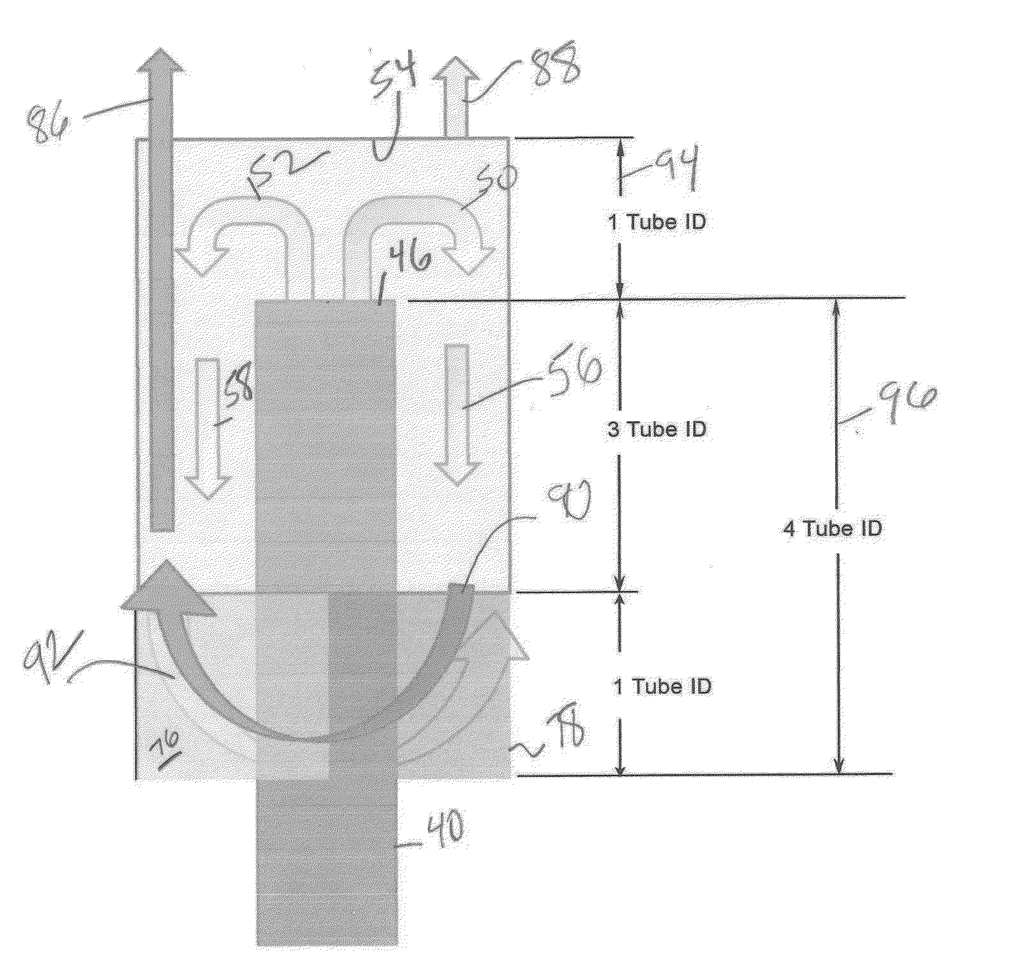
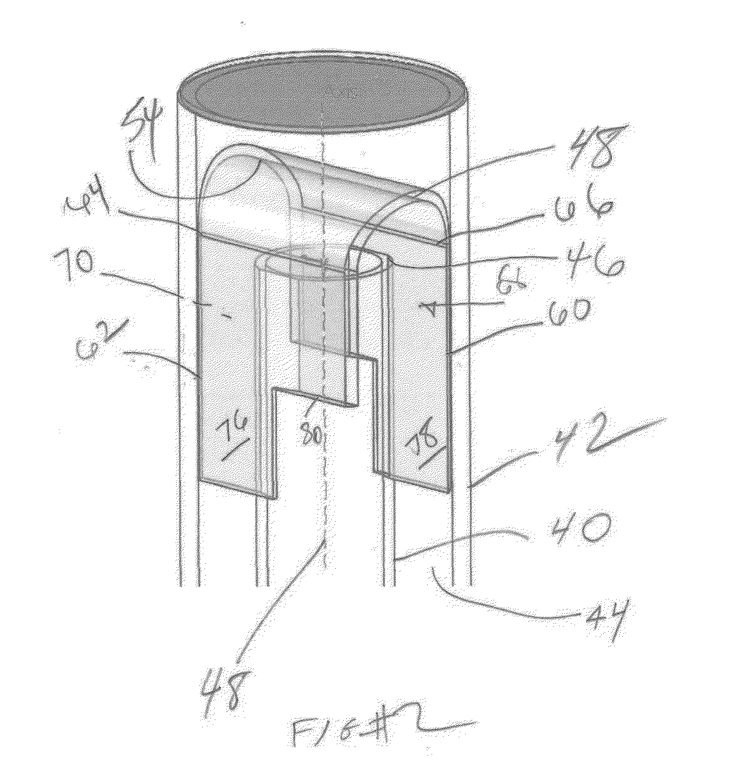
[0013]The basic debris removal tool design is illustrated in U.S. Pat. No. 7,472,745 FIG. 1 and the basic operation of the device covered there is incorporated by reference as if fully set forth here. Debris laden flow is induced with an eductor (not shown) into inlet tube 40 that is preferably centrally positioned in housing 42 to define an annular debris collection volume 44 that has a closed bottom (not shown) to retain the debris. The debris laden fluid makes a 180 degree turn after exiting through the open top 46 of tube 40 and impacting member 48 that is preferably a cylinder shape cut along the long axis and transversely mounted to the axis 48 of inlet tube 40. The flow regime for FIG. 2 is schematically illustrated in FIG. 6 showing arrows 50 and 52 as a split of the uphole debris laden flow in tube 40 as the top 46 is reached and there is impact with the curved surface 54 of member 48. Arrows 56 and 58 represent the tow discrete downhole directed flow paths defined by paral...


PUM


Abstract

A debris removal device for subterranean use features a debris laden inlet tube within a housing to define a debris collection space at the lower end of the housing. An eductor draws the debris laden fluid to the top of the inlet tube where the flow stream is returned to a downhole direction with discrete passages formed between the housing and the inlet tube by spaced parallel plates. The plates feature extending tabs on diametrically opposed lower ends of the plates. As a result flow heading back downhole can release debris and turn back uphole in passages defined between the outside of the plates and the inside wall of the housing. The tabs allow the flow turning uphole to make a greater radius turn because of a crossing over effect created by the tabs. There is less turbulence and narrower width to the flowing stream going uphole.

Description


Claims


Application Information

Patent Timeline
Owner BAKER HUGHES INC
Why Eureka
Try Eureka