Windmill generator associated with a construction

a technology of wind turbine generator and construction, which is applied in the direction of wind turbine generator, motor, sustainable building, etc., can solve the problems of wind turbine generator not taking advantage of the geometry or design of the building structure, the barrel is significantly reduced, and the final cost of wind turbine generation is higher. , to achieve the effect of reducing the turbulence of the inciden

Inactive Publication Date: 2019-01-24
CIANNI LUCIANO ENRIQUE +2
View PDF7 Cites 8 Cited by
  • Summary
  • Abstract
  • Description
  • Claims
  • Application Information

AI Technical Summary

Benefits of technology

[0021]It is an object of this instant invention to maximize the wind energy surrounding a construction or building which has its volume submerged within an airstream.
[0027]It is also an object of this instant invention to provide a structure or construction whose profile allows to reduce the turbulence of the thereon incident airflow and direct said airstream and capable of directing said airstream towards the vertical axis rotor inlet or intake of the generator(s) associated with said building.
[0028]A further object of this invention is that at least one windmill generator associated with the construction has at least one screen capable of providing soundproofing, as well as a protection against accidents due to physical exposure of people to the rotor and an aesthetic concealment by harmonizing the structure's visual appearance concealing said windmill
[0029]It is also an object of this instant invention to provide the less possible an downstream turbulence of the airstream leaving a first building in order to preserve the potential wind energy to be used by a second building placed downstream of the first building; in this way it is possible according to this invention to build whole neighbourhoods of dwellings and other constructions, each one with its own windmill generated electricity, which may also be integrated into a network or energy distribution grid covering this whole same neighbourhood.
[0030]It is a further object of this invention a building designed to cooperatively optimize the use of low cost windmill generators such as WAWT, by means of inserting into the building's volume the inactive portion of the rotor of said windmill which are not active and receiving the airflow which makes them turn, preventing said inactive portion to act as a brake to the rotational movement of said rotor and offering only the active part thereof to the incident wind direction.

Problems solved by technology

Therefore, the generator does not take advantage of the geometry or design of the building's structure, and the result of this is that known windmills performs independently of the actual building's design.
It is also known that even with all current developments, wind power generation has a higher final cost when compared to a traditional electricity generation, especially in the stages in which the price of the oil barrel decreases significantly.
This is due to the high initial installation and maintenance costs of wind generated electricity.
Precisely most of existing inconveniencies are detected when considering the issue of preventive maintenance of current horizontal axis windmills, since each blade of these large diameter rotors needs special equipment for inspection and eventual replacement, involving very steep disbursements.
As above mentioned, wind farm facilities currently reflect a compromise between environmental pollution and a very high noise level developed by these facilities, hence it is not easy, and sometimes impossible, to consider having wind-farms coexisting or placed in proximity to habitable areas, hence subsists the problem of laying and transporting the generated electricity (distribution networks) to the end user.
Another serious problem consists in regulating the airflow impinging on the rotor of the vertical axis windmill.
In effect, whenever wind gusts develops wind speeds which may damage the rotors, according to the know technology there is no other resource than to feather the blades of the rotor, being the quite difficult to achieve with vertical axis devices, while on the other hand, if the wind's speed falls under a determined value, these devices may lose efficiency by not having an induced airflow strong enough to allow operating at a sustainable speed.
But a major problem facing known electricity generators driven by state of the art windmills and associated with existing constructions or buildings is that they are unable to efficiently channel the immense airflow towards suitable windmills providing an average steady laminar airflow, and even capable of increasing the wind's speed impinging on the rotors, hence they proved unable to take full advantage of the existing potential energy carried by the wind surrounding a building.
Further, it is also known that the mass of air incidental on a building moves at a faster rate the higher said building so having a design that manages to efficiently capture that energy irrespective of the building's height is also a problem pending to be solved.
The majority of the current constructions or buildings have a front surface against which the wind airflow collides causing an increased turbulent regime, especially at the building's edges or vertex, creating the detachment of the airflow from the building's surface, thus destroying any laminar airflow.
As a rule, the geometry of current constructions causes an increase of the airflow turbulence at its downwind edges (that is, the wind flow leaving the building's surface), so that another second construction having its own associated windmills cannot be placed downstream in proximity to the first building turbulent airflow leaving the upstream first building, hence a considerable distance must be provided between said two building or constructions.

Method used


Image

  • Windmill generator associated with a construction
  • Windmill generator associated with a construction
  • Windmill generator associated with a construction

Examples


Embodiment Construction

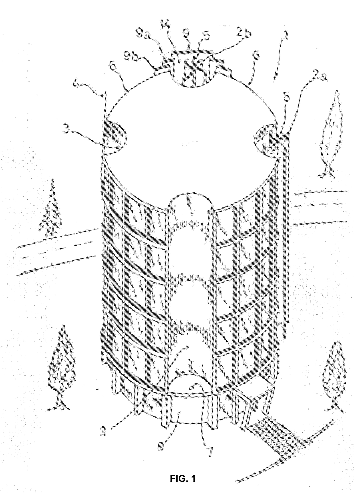
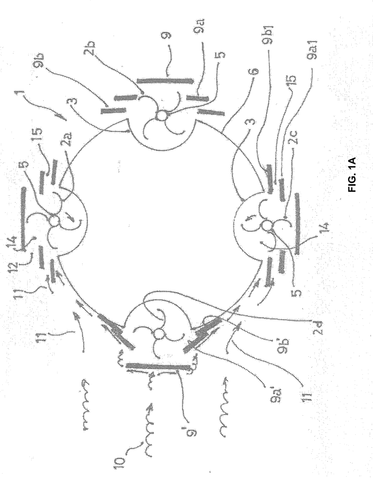
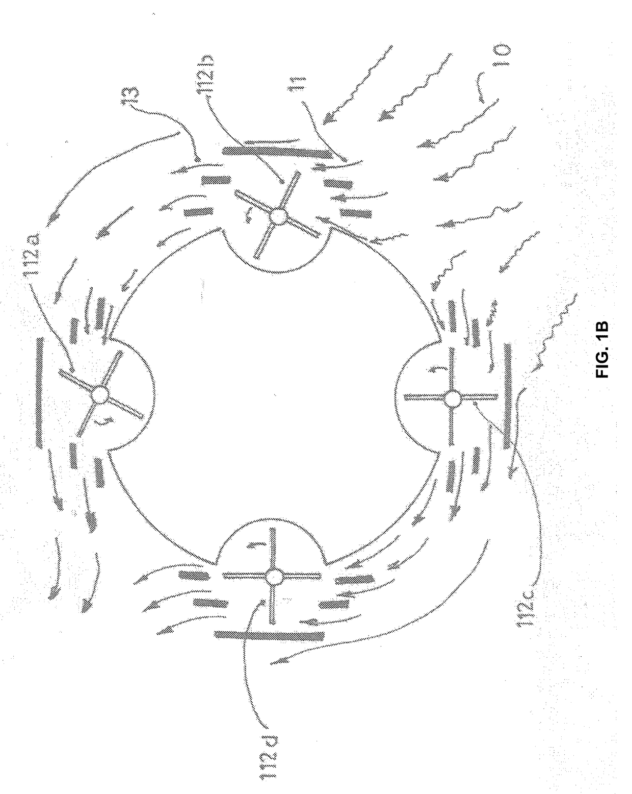
[0033]in order to exemplify the preferred embodiments of this instant invention, the following drawings are attached, in support of the description thereof below given. These exemplary embodiments must be considered as one of the possible constructions of this invention, hence it is not appropriate to assign to them any limiting value of the scope of this invention, which is determined by the first claims below appended.

[0034]according to this instant invention, it can be considered that any construction built according to its teachings will prove more efficient in the generation of energy and in its task of generating as little as possible downstream turbulence in the airflow the more aerodynamic said constructions are in their final design. This is the reason why according to this invention, it is preferred to consider cylindrical buildings or constructions with a tapered horizontal cross section.

[0035]This instant invention is applicable to an ample variety of building's profiles...


PUM


Abstract

A construction (1) defining a volume submerged in an air-stream (10), with at least one surface (6) against which the air current impinges, directing, acceleration and laminating an air-flow against the lateral (6) of the construction (6) having at least one wind-mill generator (2) attached to said lateral (6) in an area where there is still no separation of said laminar air-flow (11) form the construction (1). Faced with said generator (2), is arranged at least one plate (9), the wind generator (2) being positioned between said plate (9) and said portion of the lateral wall, determining a tunnel (14) with an air inlet and outlet of the air-stream impinging on the blades of the wind-mill generator (2). The inlet of the air-stream into said tunnel (14) directed towards the blades of the wind-mill generator is placed adjacent the largest section of the perimeter of said construction (1), perpendicular to the direction of incidence of the wind-stream.

Description

FIELD OF THE INVENTION[0001]This instant invention finds its field of application in the electric energy generation extracted from the potential energy contained in an airflow or airstream. More specifically, this instant invention is related to an airflow submerged construction, directing and accelerating said airflow through at least a windmill generator associated with said construction. By the term “construction” it is intended all kind of dwellings, buildings, factories, stores, sheds, or the like.BACKGROUND OF THE INVENTION[0002]Since ancient times man has managed to extract the powerful energy carried by an airflow, converting or transforming same into mechanical energy for several purposes. Classic examples of this are the windmills, particularly those found in the Netherlands, Normandy and the Bay of Biscay, which are airfoils, namely sail cloth or the like stretched over suitable frames, rotating on a horizontal axis and placed in suitable position regarding the wind direc...

Claims


Application Information

Patent Timeline
Patent Type & Authority Applications(United States)
IPC IPC(8): F03D3/04F03D13/20F03D9/45
CPCF03D3/0418F03D13/20F03D9/45F05B2240/9112F03D9/43Y02B10/30Y02E10/728Y02E10/74
Inventor BLANCO, ROBERTO HORACIOKLARENBERG, ALEJANDRO JOSEPIZARRO, JUAN PABLOCIANNI, LUCIANO ENRIQUEBOSIO BLANCO, CARLO CONRADO
Owner CIANNI LUCIANO ENRIQUE
Why Eureka
Try Eureka