Apparatus and method for making optical fiber

a technology of optical fiber and apparatus, applied in the field of optical fiber making apparatus, can solve the problems of not being able to meet the requirements of mass-production of coated optical fibers, not being able to apply as a mass-producing method, etc., and achieve the effect of reducing the loss of transmission and reducing the intensity of rayleigh scattering

Inactive Publication Date: 2005-02-08
SUMITOMO ELECTRIC IND LTD
View PDF14 Cites 9 Cited by
  • Summary
  • Abstract
  • Description
  • Claims
  • Application Information

AI Technical Summary

Benefits of technology

In view of the points mentioned above, it is an object of the present invention to provide a method and apparatus for making an optical fiber, which is applicable to the mass production of coated optical fibers whose surface is coated with a resin when making optical fibers whose transmission loss is lowered by reducing its Rayleigh scattering intensity.

Problems solved by technology

HEI 10-25127 is not suitable for mass-producing coated optical fibers, since the resin coated on the optical fiber surface is burned by the heat at the time of reheating.
Though the optical fiber may be reheated while in an uncoated state, it is not applicable as a mass-producing method due to damages at the time of handling the optical fiber and the like.

Method used


Image

  • Apparatus and method for making optical fiber
  • Apparatus and method for making optical fiber
  • Apparatus and method for making optical fiber

Examples


first embodiment

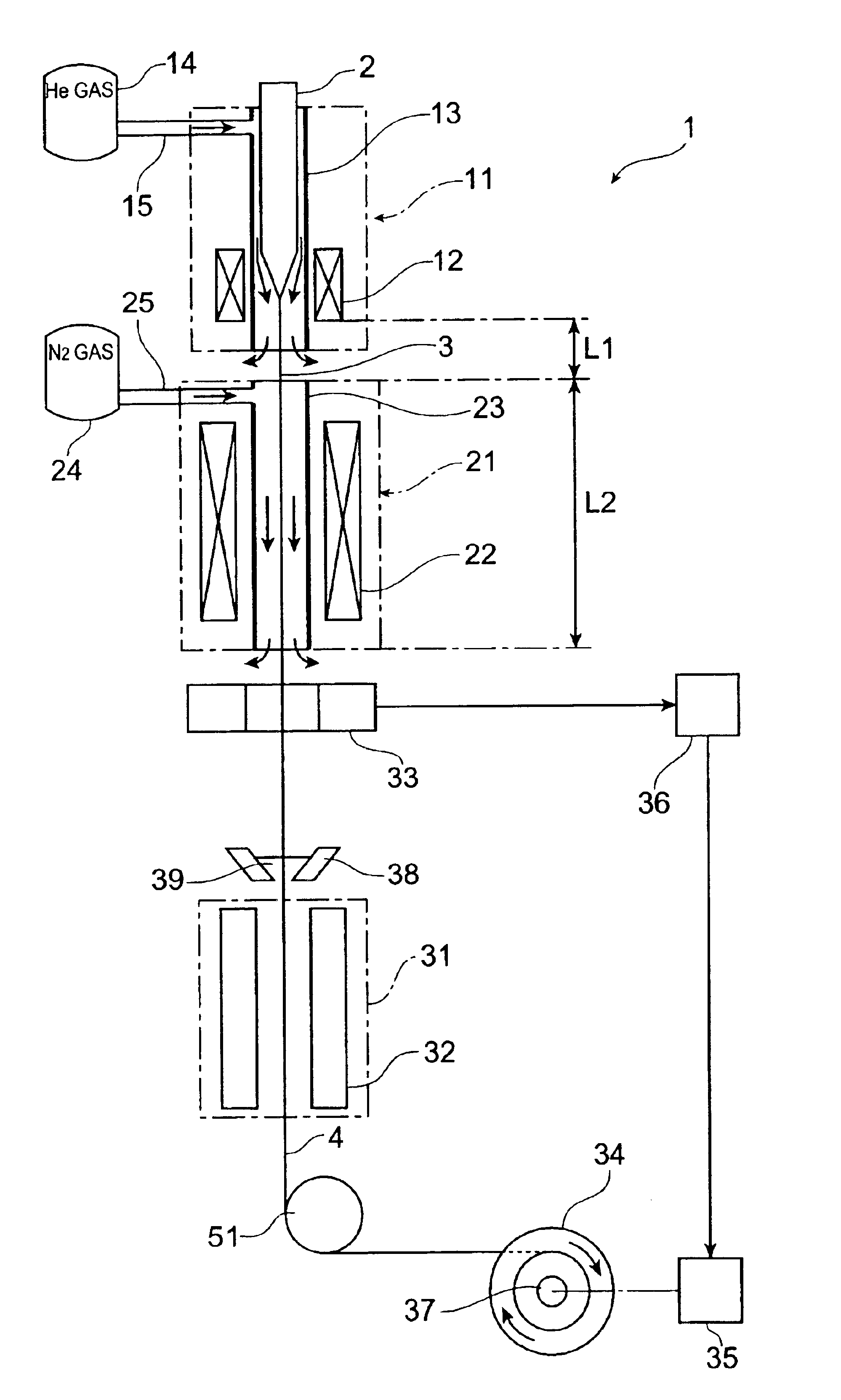
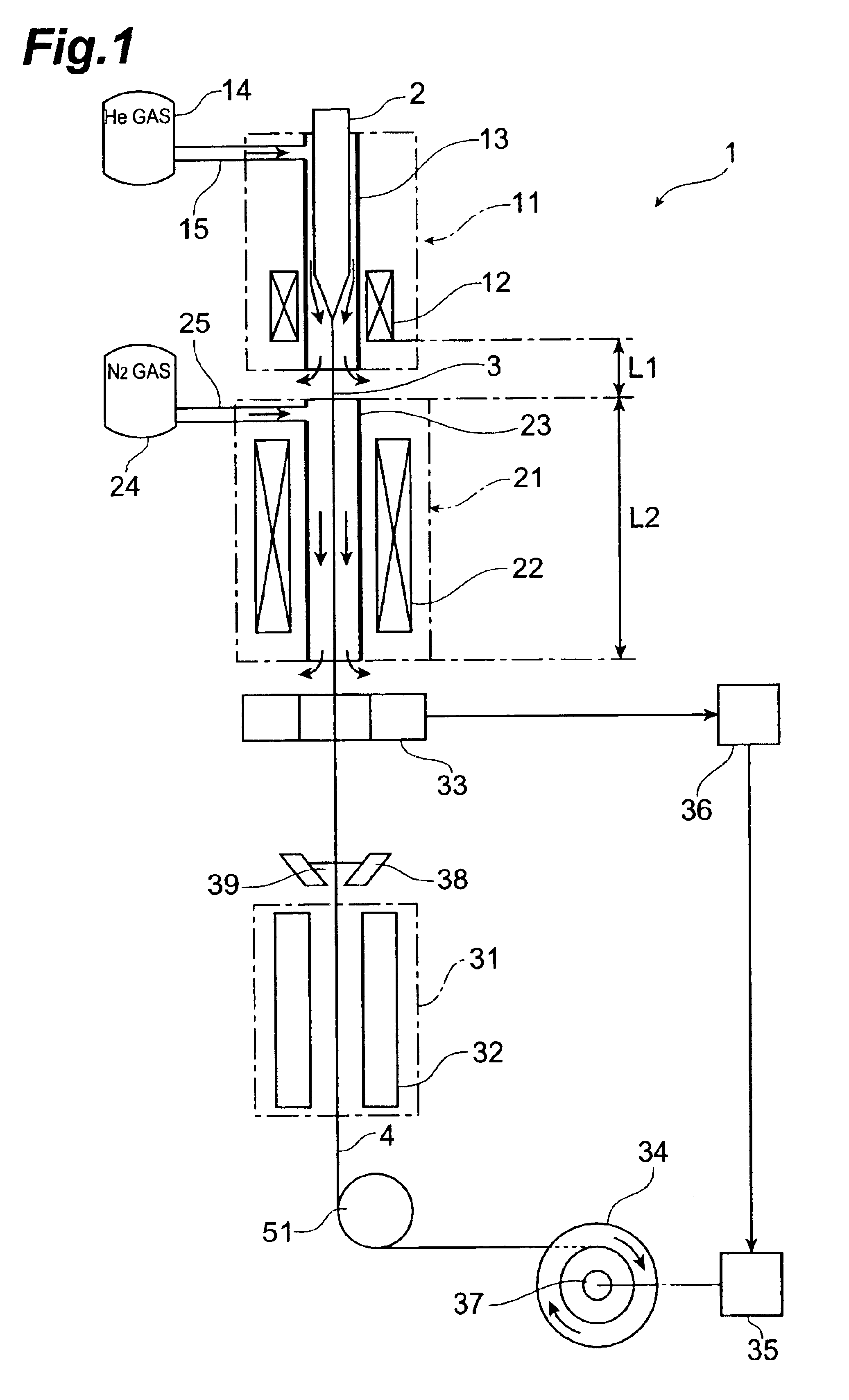
To begin with, a first embodiment of the apparatus and method for making an optical fiber in accordance with the present invention will be explained with reference to FIG. 1.

A drawing apparatus 1 is a drawing apparatus for silica type optical fibers, having a drawing furnace 11, a heating furnace 21 for annealing, and a resin curing section 31 which are disposed in this order in the drawing direction of an optical fiber preform 2 (downward in FIG. 1). The optical fiber preform 2 held by a preform supply apparatus (not depicted) is supplied to the drawing furnace 11, and the lower end of the optical fiber preform 2 is heated and softened by a heater 12 within the drawing furnace 11, whereby an optical fiber 3 is drawn. The drawing furnace 11 has a muffle tube 13 configured such that an He gas supply passage 15 from an He gas supply section 14 is connected thereto, so as to supply He gas as a first gas into the muffle tube 13 of the drawing furnace 11, whereby an He gas atmosphere is ...
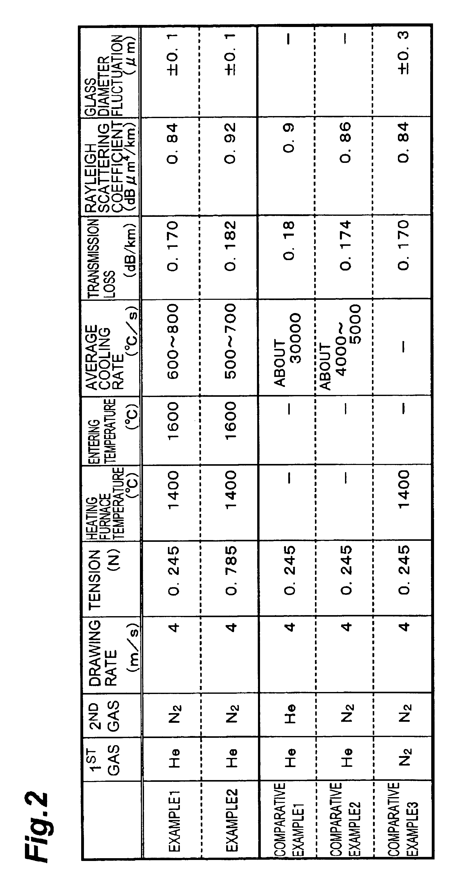
examples 1 and 2

are examples in conformity to the apparatus and method for making an optical fiber in accordance with the above-mentioned first embodiment, whereas Comparative Examples 1 to 3 are comparative examples carried out for comparison with the above-mentioned Examples in conformity to the apparatus and method for making an optical fiber in accordance with the first embodiment.

example 1

Using a heating furnace having a muffle tube (with an inner peripheral diameter of about 30 mm) in which L1=0.4 m and L2 =1.0 m, an optical fiber was drawn. The distance (L4) between the drawing furnace and the heating furnace was set to 0.05 m. The optical fiber preform to be drawn had a core portion constituted by pure silica glass, and a cladding portion constituted by fluorine-doped glass. The drawing rate was 4 m / s, the drawing tension was 0.245 N (25 gf), and the temperature of the heating furnace (the surface temperature of the inner peripheral face of the muffle tube) was 1400° C. The temperature (entering temperature) of the optical fiber immediately before entering the heating furnace was about 1600° C. in terms of the surface temperature of optical fiber. As can be seen from characteristic a in FIG. 3B, the optical fiber had such a temperature distribution (calculated value) that it was annealed as being held at a temperature of 1600° C. or thereabout within the heating f...


PUM

PropertyMeasurementUnit
temperatureaaaaaaaaaa

Abstract

A drawing apparatus 1 has a drawing furnace 11, a heating furnace 21, and a resin curing section 31. The drawing furnace 11 has a muffle tube 13 to which an He gas supply passage 15 from an He gas supply section 14 is connected so as to supply He gas. The optical fiber 3 drawn upon heating by the drawing furnace 11 is fed to the heating furnace 21, whereby a predetermined part of the optical fiber 3 is annealed at a predetermined cooling rate. The heating furnace 21 has a muffle tube 23 to which an N2 gas supply passage 25 from an N2 gas supply section 24 is connected so as to supply N2 gas. Thereafter, the optical fiber 3 is coated with a UV resin 39 by a coating die 38, and the UV resin 39 is cured in the resin curing section 31, whereby a coated optical fiber 4 is formed.

Description

RELATED APPLICATIONThis is a continuation-in-part application of application serial no. PCT / JP00 / 03411 filed on May 26, 2000, now pending.BACKGROUND OF THE INVENTION1. Field of the InventionThe present invention relates to a method and apparatus for making an optical fiber whose transmission loss is lowered by reducing its Rayleigh scattering intensity.2. Related Background ArtAs a method of making an optical fiber whose transmission loss is lowered by reducing its Rayleigh scattering loss, one disclosed in Japanese Patent Application Laid-Open No. HEI 10-25127 has been known, for example. In this manufacturing method, an optical fiber preform is drawn upon heating so as to prepare an intermediate optical fiber, which is then reheated so as to be subjected to a heat treatment, whereby the reheating lowers the virtual temperature (the temperature to which the randomness of the state of atomic arrangement within the glass corresponds) due to the structural relaxation (rearrangement of...

Claims


Application Information

Patent Timeline
Patent Type & Authority Patents(United States)
IPC IPC(8): C03B37/02C03B37/027C03B37/029
CPCC03B37/02718C03B37/029C03B2205/90C03B2205/56C03B2205/40
Inventor NAGAYAMA, KATSUYAOHGA, YUICHISAITOH, TATSUHIKOTAKAMIZAWA, HIROSHI
Owner SUMITOMO ELECTRIC IND LTD
Why Eureka
Try Eureka