Burner for a Gas Turbine

a gas turbine and burner technology, applied in the direction of burners, combustion types, combustion processes, etc., can solve the problems of high pollutant emission levels of premix burners, and achieve the effects of reducing turbulence in the spray cone, uniform velocity profile, and small angl

Inactive Publication Date: 2007-09-06
ANSALDO ENERGIA SWITZERLAND AG
View PDF5 Cites 9 Cited by
  • Summary
  • Abstract
  • Description
  • Claims
  • Application Information

AI Technical Summary

Benefits of technology

[0026] The internal geometry of the outlet passages, and in particular the narrowing by a given angle prior to the outlet opening into the swirled generator, reduce turbulence in the spray cone and produce a smaller angle at which the spray cone diverges. This makes it possible to produce a spray cone with a more uniform velocity profile. Finally, the increased flow stability in the spray cone leads to improved positioning of the fuel in the premix burner and therefore to improved flame conditions.
[0027] In a further embodiment, the second cylindrical sections of the outlet passages each have a length which amounts to at most five times the diameter of the outlet openings. A length to diameter ratio of this type contributes to improving the flow profile and flow stability. In one specific embodiment, the outlet openings have a diameter of 0.5-1.5 mm.
[0028] In a further preferred embodiment of the invention, together with the above-mentioned internal geometries of the outlet passages of the nozzle, the outer wall of the nozzle tip is rounded in form, preferably oval in cross section. The rounded form produces further benefits with regard to the incoming flow of air, since the air flow can uniformly follow this shape of the outer wall of the nozzle, and correspondingly less turbulence or recirculation is produced downstream of the nozzle. This increases the homogeneity of the mixing of air and fuel, which lowers the NOx emission levels.
[0029] A reduced recirculation downstream of the nozzle finally also influences the swirl at the end of the cylindrical mixing section and leads to aerodynamic stabilizing of the flame in the combustion chamber. Stabilizing of this nature allows a greater freedom of choice with regard to the operating parameters of the burner.

Problems solved by technology

An excessively large orientation angle of the spray cones with respect to the longitudinal axis of the swirl generator, on the other hand, would lead to the atomised fuel coming into contact with the incoming air flow at an earlier stage and being diverted toward the center of the swirl generator by the air flow.
This is because if the atomised fuel comes too close to the center, higher pollutant emission levels result for the premix burner.

Method used


Image

  • Burner for a Gas Turbine
  • Burner for a Gas Turbine
  • Burner for a Gas Turbine

Examples


Embodiment Construction

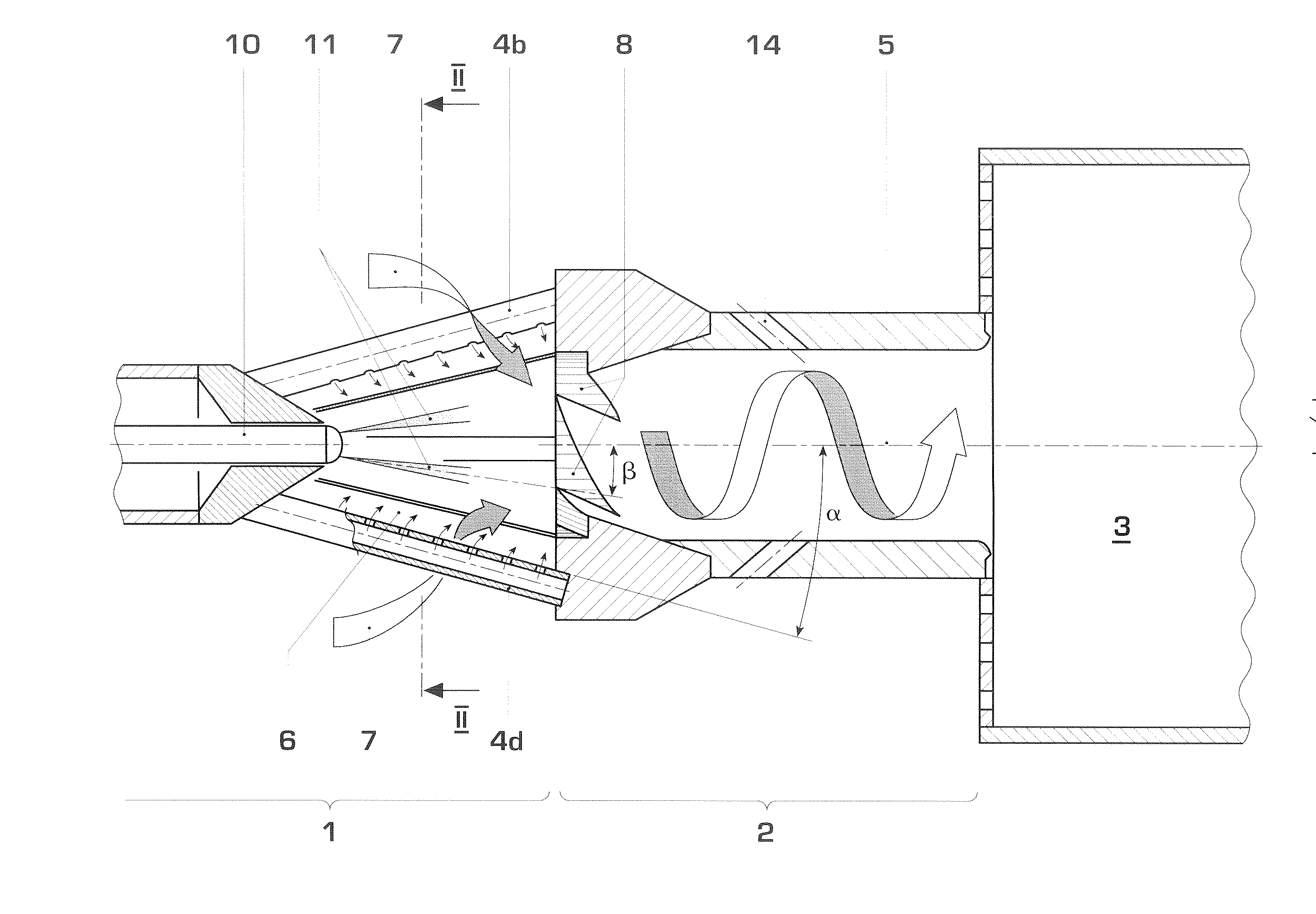
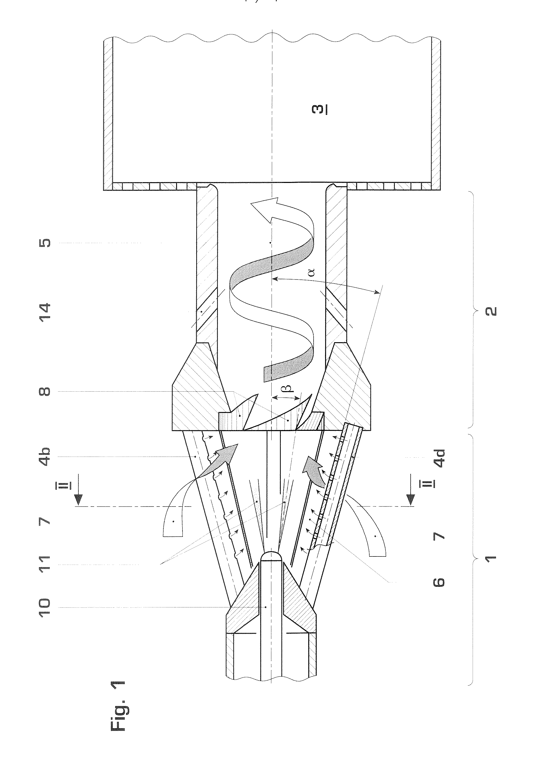
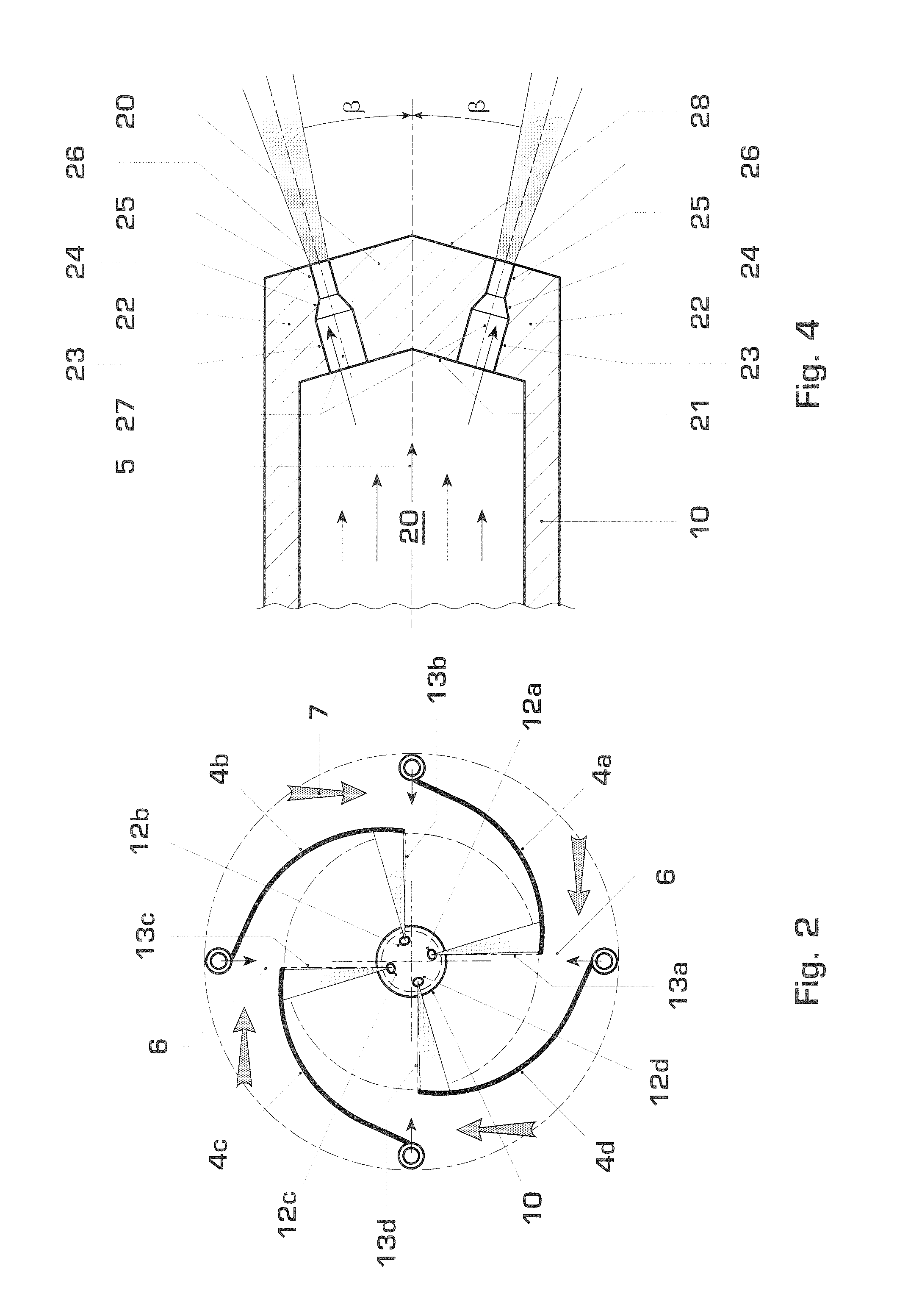
[0041]FIG. 1 shows a premix burner, for example for a gas turbine. It has a conical swirl generator 1 and a subsequent cylindrical mixing section 2, which expands into a combustion chamber space 3. In this example, the swirl generator 1 includes four interleaved cone parts 4a, 4b, 4c, 4d, of which cone parts 4b and 4d can be seen in FIG. 1. The individual longitudinal axes of the cone parts are in each case arranged offset with respect to one another and with respect to the longitudinal axis 5 of the swirl generator, as can be seen from FIG. 2. The cone parts 4a-d in each case run at an angle α with respect to the longitudinal axis 5 of the swirl generator 1. They in each case form spacers 6 between one another along their longitudinal edges, which spacers 6 are used for the introduction of compressed combustion air, the flow profile of which is indicated by the arrows 7. Metal sheets 8 are arranged at the outlet of the swirl generator 1 in order to form transition passages into the...


PUM


Abstract

A premix burner, for example for a gas turbine, having a conical swirl generator (1) and a cylindrical mixing section (2) which follows it in the direction of flow, includes a high-pressure atomizer nozzle (10) with one or more fuel feed passages. The high-pressure atomizer nozzle (10) includes at least two outlet passages, through which liquid fuel enters the swirl generator (1), these passages being arranged off-center with respect to the longitudinal axis of the nozzle and being configured in such a way that the spray cone (11) of the fuel is oriented at an angle (β) with respect to the longitudinal axis of the swirl generator (1) which is smaller than the cone half-angle (α) of the swirl generator (1). The outlet passages in particular have an internal geometry with a conically narrowed section.

Description

[0001] This application is a Continuation of, and claims priority under 35 U.S.C. § 120 to, International application number PCT / EP2005 / 055098, filed 7 Oct. 2005, and claims priority therethrough to Swiss application number 01710 / 04, filed 18 Oct. 2004, the entireties of which are incorporated by reference herein.BACKGROUND [0002] 1. Field of Endeavor [0003] The disclosure relates to a premix burner for a gas turbine, in particular to a nozzle for atomising liquid fuel in a premix burner with a conical swirl generator and a subsequent cylindrical mixing section. [0004] 2. Brief Description of the Related Art [0005] Premix burners with a conical swirl generator and a subsequent cylindrical mixing section are known, for example, from EP918191. The swirl generator, which serves as a premix section, has conical interleaved sections, the longitudinal axes of which are in each case offset with respect to one another. Compressed combustion air passes through tangential inflow passages betw...

Claims


Application Information

Patent Timeline
Patent Type & Authority Applications(United States)
IPC IPC(8): F23D14/62
CPCF23C7/002F23C2900/07002F23R3/343F23D11/38F23D11/24
Inventor OOMENS, GIJSBERTUSPAIKERT, BETTINAFLOHR, PETERSTEINBACH, CHRISTIAN
Owner ANSALDO ENERGIA SWITZERLAND AG
Why Eureka
Try Eureka