Single Duct Silencing Terminal Unit

a terminal unit and single duct technology, applied in the direction of ducting arrangement, lighting and heating apparatus, heating types, etc., can solve the problems of affecting the noise level generated, affecting the turbulence and air pressure created inside the ductwork, and specifications that do not take into account the system effects produced, etc., to achieve the effect of minimizing turbulence, reducing turbulence, and superior attenuation properties

Inactive Publication Date: 2008-09-18
E H PRICE
View PDF7 Cites 10 Cited by
  • Summary
  • Abstract
  • Description
  • Claims
  • Application Information

AI Technical Summary

Benefits of technology

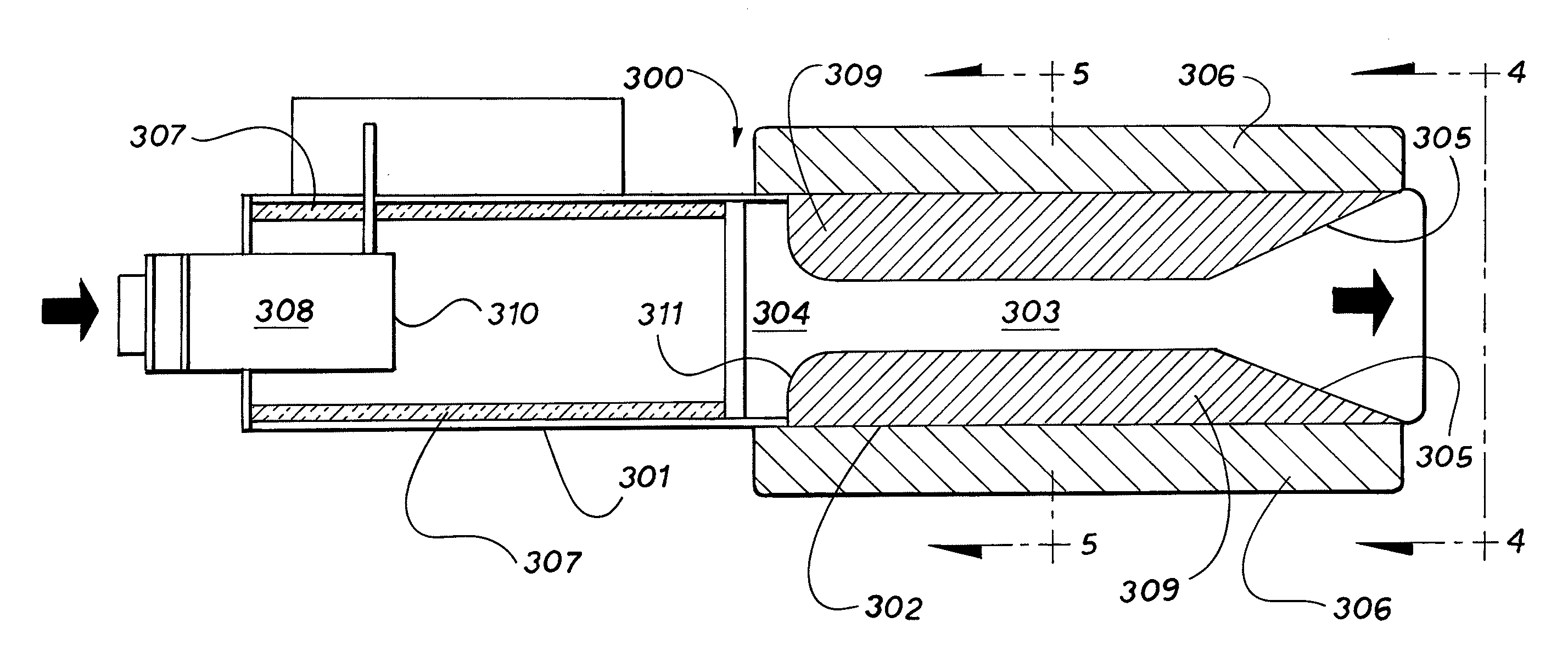
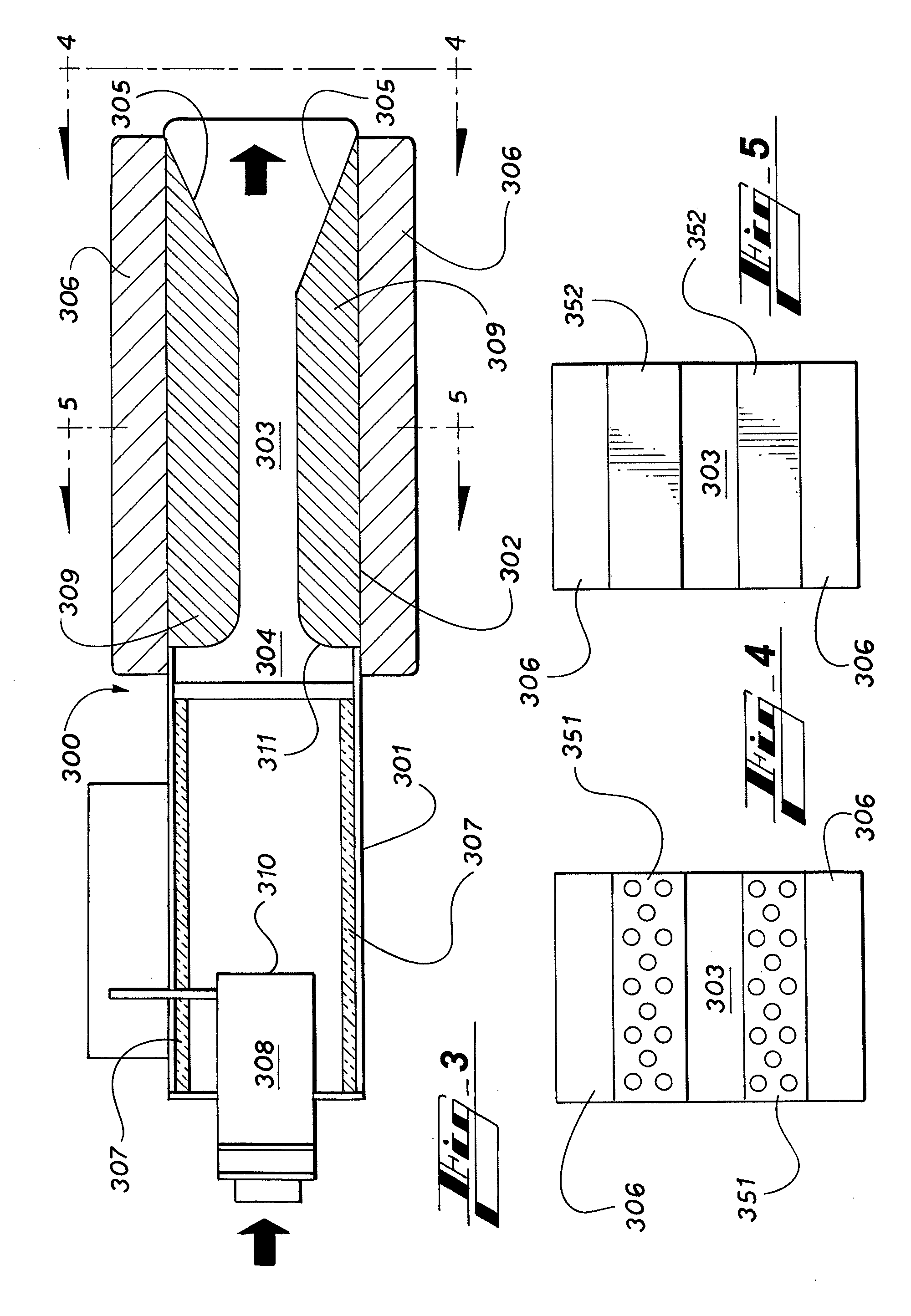
[0012]Some embodiments of the invention include thicker insulation around the plenum of the SDSTU than prior art SDTUs and thus provide superior attenuation properties.
[0013]In some embodiments, the length of the “discharge region” following the inlet duct of the SDSTU is longer than in prior art SDTUs. This provides a longer length inside the plenum for the flowing air to transition from the high-pressure, high-velocity ductwork into the SDSTU. This, in turn, allows for less turbulence as the flowing air moves into the silencing portion of the SDSTU.
[0014]The plenum portion of the SDSTU is closely coupled to the silencing portion of the SDSTU in some embodiments. This helps minimize turbulence within the SDSTU and minimizes the overall length of the SDSTU in comparison to the prior art combination of an SDTU, silencer, and connecting ductwork.

Problems solved by technology

For instance, the manner in which the distribution ductwork is organized in a given building installation can affect the turbulence and air pressures created inside the ductwork.
This, in turn, can affect the noise level generated by an SDTU and the acoustic performance achieved by a silencer attached thereto.
The unpredictability produced by such system effects creates uncertainty when HVAC installers are selecting SDTUs and silencers for installation in a building.
However, these specifications do not take into account the system effects produced by installing their products in an actual HVAC system.
Thus, HVAC installers generally have only marginally reliable product specifications on which they can rely and often must utilize trial-and-error methods to choose the appropriate combination of SDTUs and silencers that will meet their needs in a particular HVAC installation.

Method used


Image

  • Single Duct Silencing Terminal Unit
  • Single Duct Silencing Terminal Unit
  • Single Duct Silencing Terminal Unit

Examples


Embodiment Construction

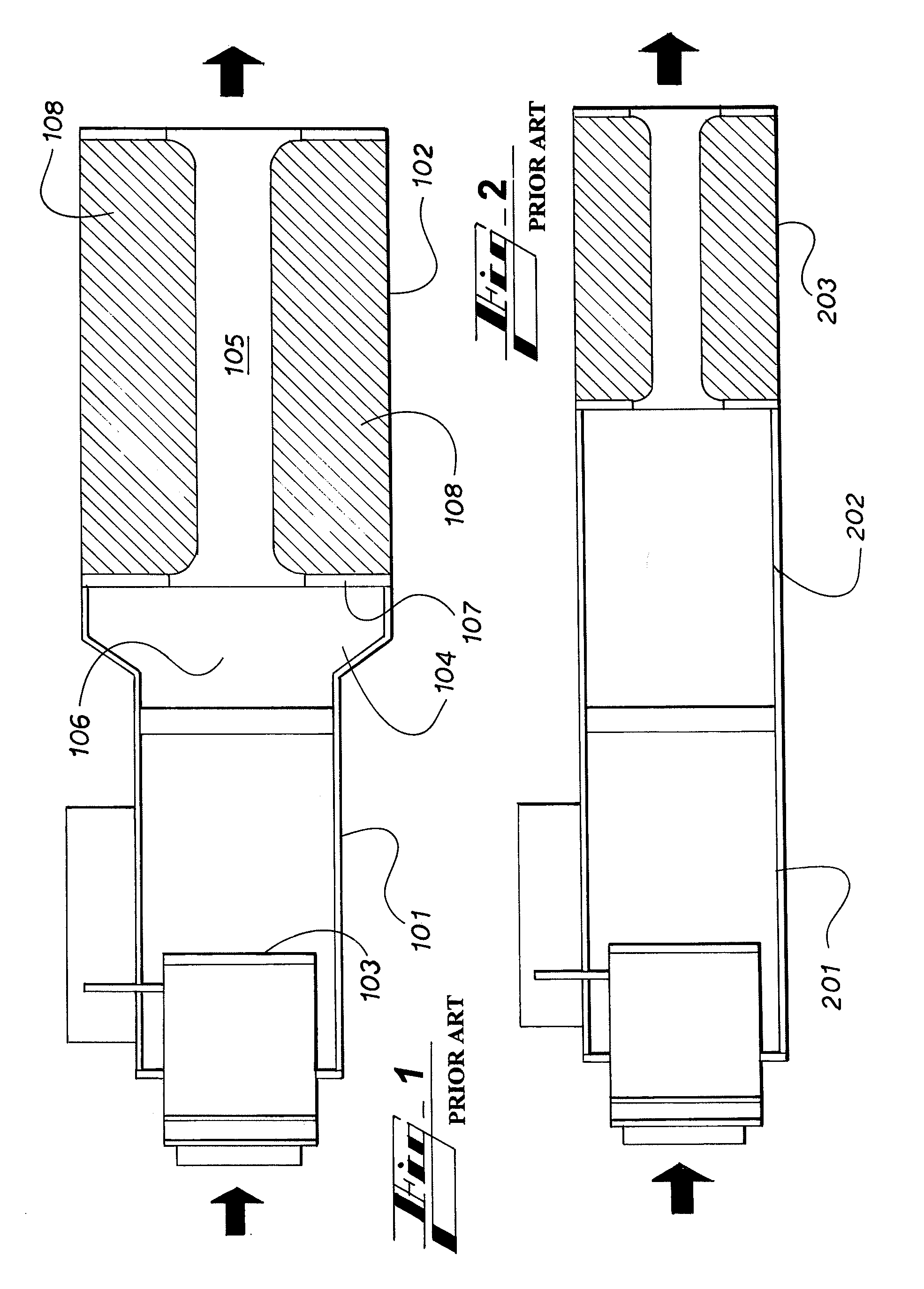
[0021]FIG. 1 is an illustration of the close-coupling of a prior art SDTU 101 with a prior art silencer 102. Such close-coupling of prior art SDTUs and silencers will produce unpredictable results because of the turbulence created when high velocity air exits the inlet duct 103 and enters the silencer 102. The wide area 104 created where the silencer 102 attaches to the SDTU 101 will create excess turbulence and noise. In addition, the cross-sectional area of the air pathway 105 of a prior art silencer 102 is typically narrower than the cross sectional area of the outlet 106 of the SDTU 101. Therefore a “nose”107 is created where the air exiting the outlet 106 collides into the baffles 108 inside the silencer 103. This too causes added turbulence and increased noise. Such noise greatly exceeds that which would be predicted based on the manufacturer's noise specifications for the SDTU 101 and silencer 102 individually.

[0022]FIG. 2 is an illustration of how prior art silencers are typ...


PUM


Abstract

An apparatus and method for attenuating the sound generated by a single duct terminal unit in an HVAC (heating, ventilating, and air conditioning) system. The apparatus utilizes internal geometry to minimize noise due to air disturbances and aerodynamic effects within the apparatus.

Description

CROSS REFERENCES TO RELATED APPLICATIONS[0001]This application claims priority to U.S. provisional application No. 60 / 895,153, filed Mar. 16, 2007, which is incorporated herein by reference.FIELD OF THE INVENTION[0002]This invention relates to an integrated single duct silencing terminal unit for HVAC (heating, ventilating, and air conditioning) systems.BACKGROUND OF THE INVENTION[0003]Commercial HVAC systems have conventionally contained “Single Duct Terminal Units” (“SDTUs”) for the purpose of providing an outlet for commercial ventilation systems into the rooms of a building or other structure equipped with an HVAC system. An SDTU typically consists of the following components: 1) inlet duct, 2) flow sensor, 3) modulation damper, and 4) insulated casing.[0004]In commercial HVAC installations, a “silencer” (or “attenuator”) is often placed downstream of an SDTU in order to attenuate the sound produced by the high-velocity air exiting the SDTU. Such silencers have typically compris...

Claims


Application Information

Patent Timeline
Patent Type & Authority Applications(United States)
IPC IPC(8): E04F17/04
CPCE04F17/04F24F13/24F24F13/0263F24F13/02
Inventor DYCK, ALFRED THEODORMCLENNAN, DUANEPATTERSON, JAMES WILLIAMBAETSEN, JOHANN JOEL EMILEGRYE, BOGNA
Owner E H PRICE
Why Eureka
Try Eureka