Sliding rack-mountable rails for rack-mountable components

a technology of rack-mounted components and sliding rails, which is applied in the direction of casings/cabinets/drawers, furniture parts, electrical appliances, etc., can solve the problems of users not being able to easily install sliding rails and servers

Active Publication Date: 2015-03-26
INNOVATION FIRST INC
View PDF11 Cites 22 Cited by
  • Summary
  • Abstract
  • Description
  • Claims
  • Application Information

AI Technical Summary

Benefits of technology

[0006]In accordance with various aspects of the invention, there is provided a support rail assembly for supporting a computer server in a rack system. The rack system typically have front and rear racks each with a plurality of openings. The support rail assembly includes a pair of rails, with each rail having an inner rail su...

Problems solved by technology

Since the rear ends of the sliding rails are often in the back of the racks, space or access...

Method used


Image

  • Sliding rack-mountable rails for rack-mountable components
  • Sliding rack-mountable rails for rack-mountable components
  • Sliding rack-mountable rails for rack-mountable components

Examples


Embodiment Construction

[0027]While the invention is susceptible to embodiments in many different forms, there are shown in the drawings and will be described in detail herein the preferred embodiments of the present invention. It should be understood, however, that the present disclosure is to be considered an exemplification of the principles of the invention and is not intended to limit the spirit or scope of the invention and / or claims of the embodiments illustrated.

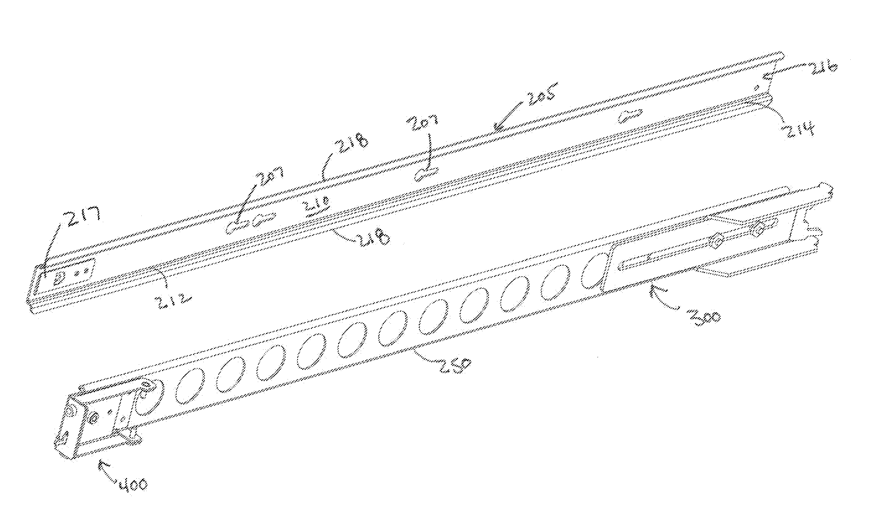
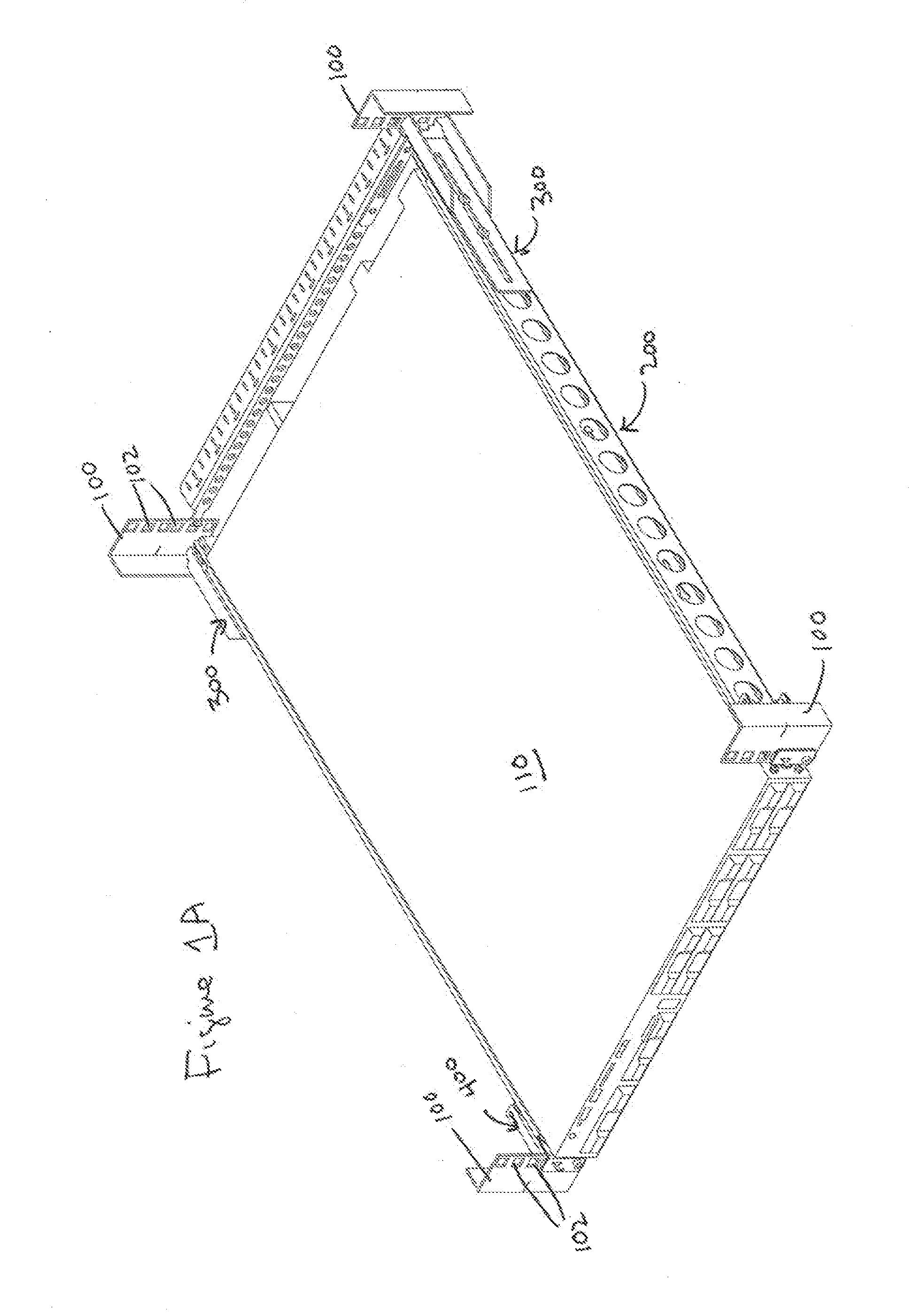
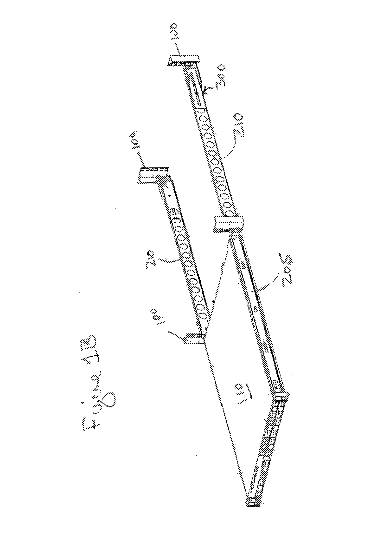
[0028]Various embodiments of the principles of the present invention are shown in FIGS. 1A-4E. The present invention comprises a sliding support shelf for electronic and related components to be supported in rack systems of various configurations. The sliding support shelf of the present invention is designed to provide support for components adapted / configured for use with rack systems, such as servers and other electronic components.

[0029]As illustrated in FIG. 1, there is shown corner racks 100 that extend vertically and that are designe...


PUM


Abstract

A support rail assembly for supporting a load in a computer rack system in accordance with one embodiment of the present invention includes a pair of rails configured to be secured to sides of computer equipment and secured to the rack system such that the computer equipment may slide into and out of the rack system. Each rail includes an inner rail slideably engaging an outer rail. The inner rail being secured to the sides of the computer equipment and the outer rail being secured to the front and rear racks. The outer rail having rear end and front end bracket that attach to the racks. Unique front end locking flanges and rear end locking flanges with rear end piloting flanges allow the outer rails to quickly pivot and lock into position.

Description

TECHNICAL FIELD[0001]The present invention relates to sliding rack-mountable rails for a rack-mounted support structure. More particularly, the invention relates to a novel sliding rail support structure designed to reduce the need for tools and time for installing the sliding rail support structure.BACKGROUND OF THE INVENTION[0002]A variety of mechanical mounting structures have been devised for various structures including computer systems. In but one example, such as a server system, a number of sub-components or servers are arranged in a central cabinet or on a rack structure. The servers are typically mounted in stacked vertical arrangements, with each server being secured within the cabinet by a sliding rail structure. The sliding rail structures permit the servers to be extracted and reinserted easily into the cabinet, such as for servicing of internal components of the servers. In general, it is desirable to allow each server to be fully or nearly fully withdrawn from the ca...

Claims


Application Information

Patent Timeline
IPC IPC(8): H05K7/18A47B88/16H05K5/02A47B88/00
CPCH05K7/183H05K5/0217A47B88/16A47B88/0085A47B88/43H05K7/1489H05K7/1421
Inventor TONTHAT, HOAINAM JAMESMIMLITCH, III, ROBERT H.VALLES, JUAN CARLOSWILSON, JAMES WHITNEY
Owner INNOVATION FIRST INC
Why Eureka
Try Eureka