Supercharge Your Innovation With Domain-Expert AI Agents!

Fire detector

a detector and fire detector technology, applied in the field of fire detectors, can solve problems such as misjudging fires, and achieve the effects of reducing noise mixing, reducing noise, and ensuring safety

Active Publication Date: 2015-03-26
HOCHIKI CORP
View PDF4 Cites 0 Cited by
  • Summary
  • Abstract
  • Description
  • Claims
  • Application Information

AI Technical Summary

Benefits of technology

The fire detector described in this patent has several technical effects. Firstly, it uses a method to stop and start the light emission multiple times during a set smoke detection operation time, and detects the light reception signals at each stop as a zero-point signal. This allows for accurate noise assessment and removal processing without missing the occurrence of varying noise. Secondly, the light emission periods are set to periods that differ from the noise periods, which reduces the degree of noise mixing with the smoke light reception signal. Thirdly, the noise assessing-processing portion performs a predetermined noise removal processing based on the noise assessment modes, which allows for reliable assessment of various types of noise and inhibits the effect of noise on the fire judgment. Fourthly, by repeating stopping and starting of light emission and finding the smoke detection signal as an average value of the values obtained by subtracting a zero-point moving average value from each of the smoke light reception signals, it inhibits the effect of fluctuations of the smoke light reception signal due to noise and other factors, and enables stable fire judgment.

Problems solved by technology

In this kind of conventional photoelectric fire detector, in the case of noise that enters from the power supply line or noise passing through the air becoming mixed with the light reception signal output from the light-receiving portion, there is the problem of misjudging a fire due to the effect of the noise.

Method used


Image

  • Fire detector
  • Fire detector
  • Fire detector

Examples


Embodiment Construction

[0040]Hereinbelow, the embodiment of the present invention shall be described while referring to the drawings. However, the present is not limited to only the embodiment given below.

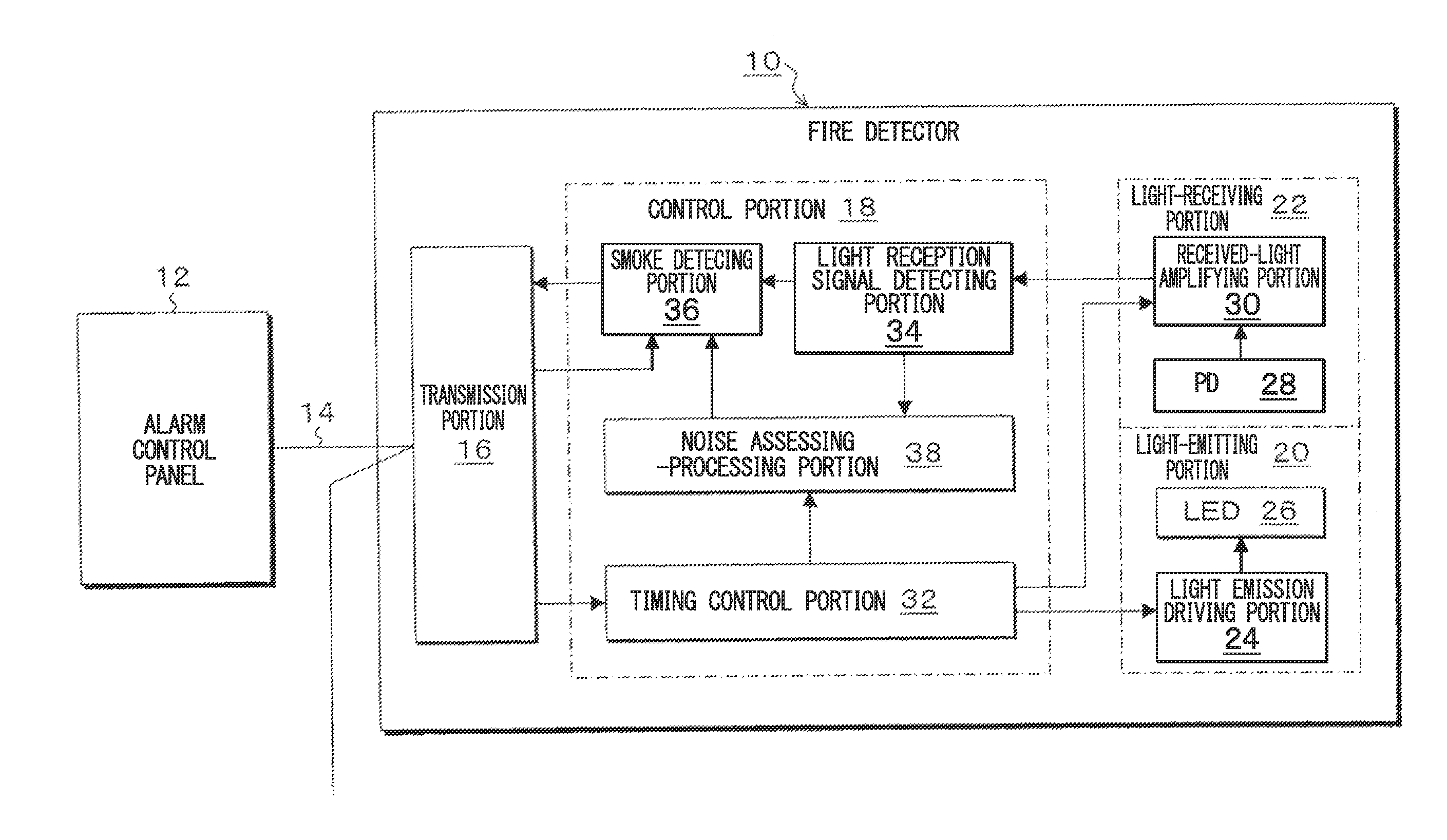
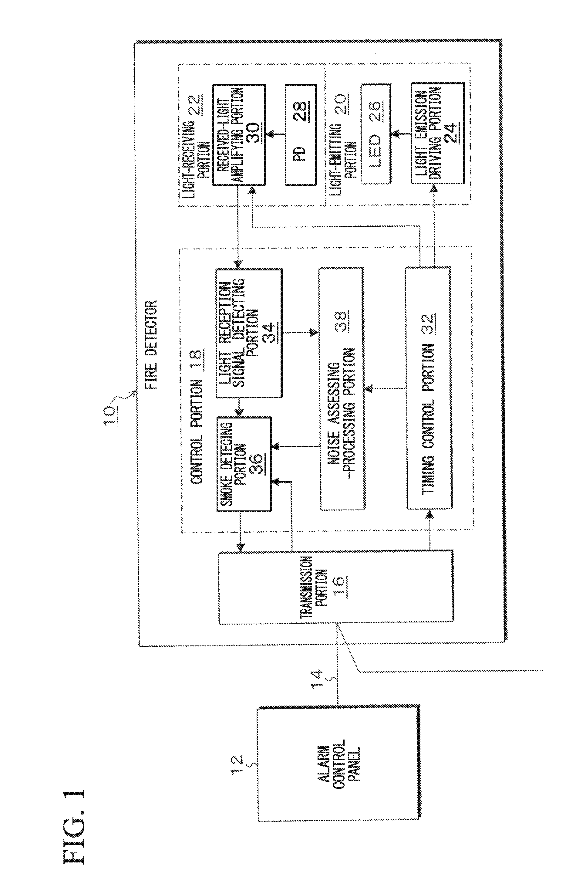
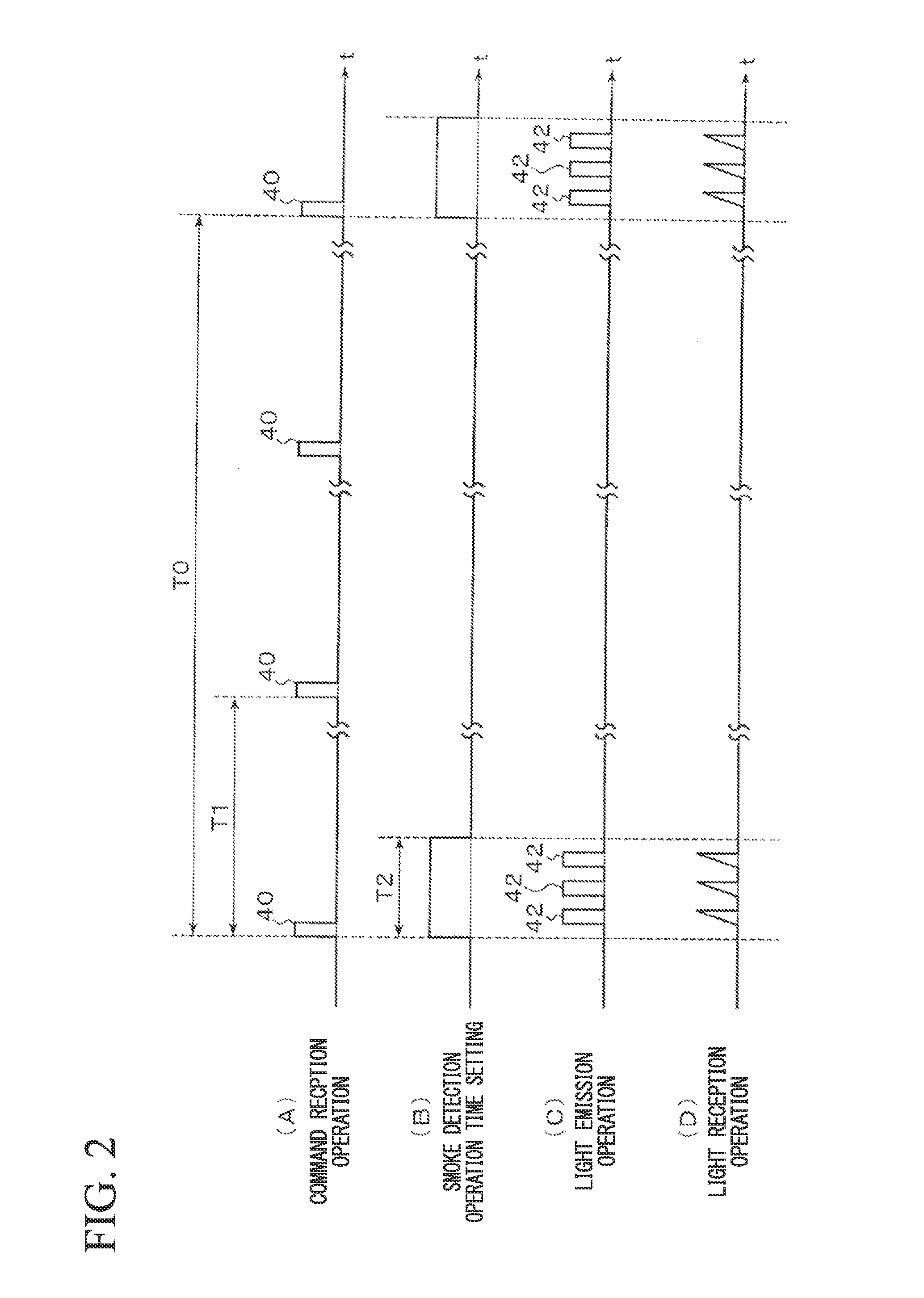
[0041]FIG. 1 is a block drawing that shows the fire detector according to one embodiment of the present invention. FIG. 2 shows the overall operation of the fire detector, and FIG. 3 breaks out the light emission operation and light reception operation of the smoke detection operation time of FIG. 2. Moreover, FIG. 4 shows the light emission operation and the light reception operation in the case of noise being mixed in.

(Schematic Configuration of Smoke Detector)

[0042]As shown in FIG. 1, the smoke detector 10 according to the present embodiment is connected to a transmission path 14 that is drawn out from an alarm control panel 12. There may be one or a plurality of fire detectors 10 connected to the transmission path 14, but hereinbelow the connection of one shall be taken for an example in order to sim...


PUM


Abstract

This fire detector is provided with a light-emitting portion that repeats stopping of light emission and light emission a plurality of number of times in predetermined light emission periods during a predetermined smoke detection operation time set for each first period; a light-receiving portion that receives the light emitted from the light-emitting portion and outputs a light reception signal during the smoke detection operation time; a light reception signal detecting portion that detects as a zero-point light reception signal the light reception signal that the light-receiving portion outputs at each light emission stop timing of the smoke detection operation time, and detects as a smoke light reception signal the light reception signal that the light-receiving portion outputs at each light emission timing; a smoke detecting portion that detects a smoke detection signal based on the zero-point light reception signals of a plurality of number of times and the smoke light reception signals of a plurality of number of times detected by the light reception signal detecting portion; and a noise assessing-processing portion that assesses the presence of mixing-in of noise to the light reception signal based on the zero-point light reception signals of a plurality of number of times and the smoke light reception signals of a plurality of number of times, and carries out noise removal processing in a case of having assessed that the noise is mixed in.

Description

TECHNICAL FIELD[0001]The present invention relates to a fire detector that detects a fire by receiving with a light-receiving portion light from a light-emitting portion that changes in accordance with smoke of a fire.[0002]Priority is claimed on Japanese Patent Application No. 2012-102441, filed Apr. 27, 2012, the content of which is incorporated herein by reference.BACKGROUND[0003]Conventionally, a photoelectric fire detector that detects smoke due to a fire receives a sampling command every fixed period from a host device such as a receiver or relay to set a predetermined smoke detecting operation time. Also, it drives a light-emitting portion one time during this smoke detecting operation time, receives with a light-receiving portion light scattered by the smoke of a fire among the light from the light-emitting portion and outputs a smoke light reception signal, and based on this smoke light reception signal, detects a smoke detecting signal corresponding to the smoke density an...

Claims


Application Information

Patent Timeline
Patent Type & Authority Applications(United States)
IPC IPC(8): G08B17/107
CPCG08B17/107G08B29/043G08B29/185G08B29/26G08B17/103
Inventor IRUMANO, HIDETAKA
Owner HOCHIKI CORP
Features
  • R&D
  • Intellectual Property
  • Life Sciences
  • Materials
  • Tech Scout
  • Unparalleled Data Quality
  • Higher Quality Content
  • 60% Fewer Hallucinations
Learn More