Image reader and image reading method

a technology of image reader and image, applied in the field of image readers, can solve the problems of method failure, streaks due to dust particle adhesion on the output image, and inability to determine the adhesion of dust particles, etc., and achieve the effect of accurate detection

Inactive Publication Date: 2005-01-04
FUJIFILM BUSINESS INNOVATION CORP
View PDF3 Cites 26 Cited by
  • Summary
  • Abstract
  • Description
  • Claims
  • Application Information

AI Technical Summary

Benefits of technology

The present invention has been made in view of the above circumstances and provides an image reader and an image reading method capable of accurately detecting, even if there may exist a density difference

Problems solved by technology

These methods, however, cannot overcome a drawback which occurs when dust particles have adhered to the reading unit, that is, a drawback in which streaks due to adhesion of dust particles appear on the output image.
When both image data pieces exceed the threshold or when they do not exceed the threshold, there is the problem that it is not determined that the dust particles have adhered even if the dust particles have adhered.
In a situation in which such a steady offset takes place, there is the problem that even if the adhesion of dust particles is determined on the basis of a difference between each image data piece in each reading position, the determination may become incorrect.
In a configuration shown in FIG. 2, however, since there takes place the offset ΔD between each reading position, the difference

Method used


Image

  • Image reader and image reading method
  • Image reader and image reading method
  • Image reader and image reading method

Examples


first embodiment

A. First Embodiment

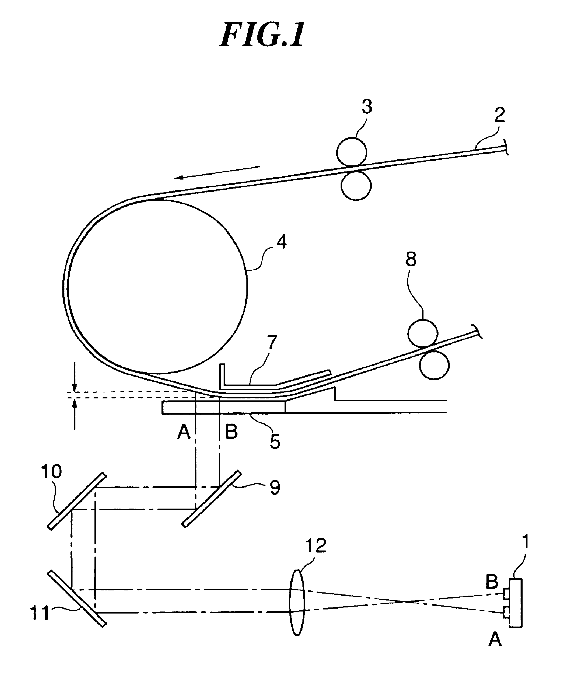
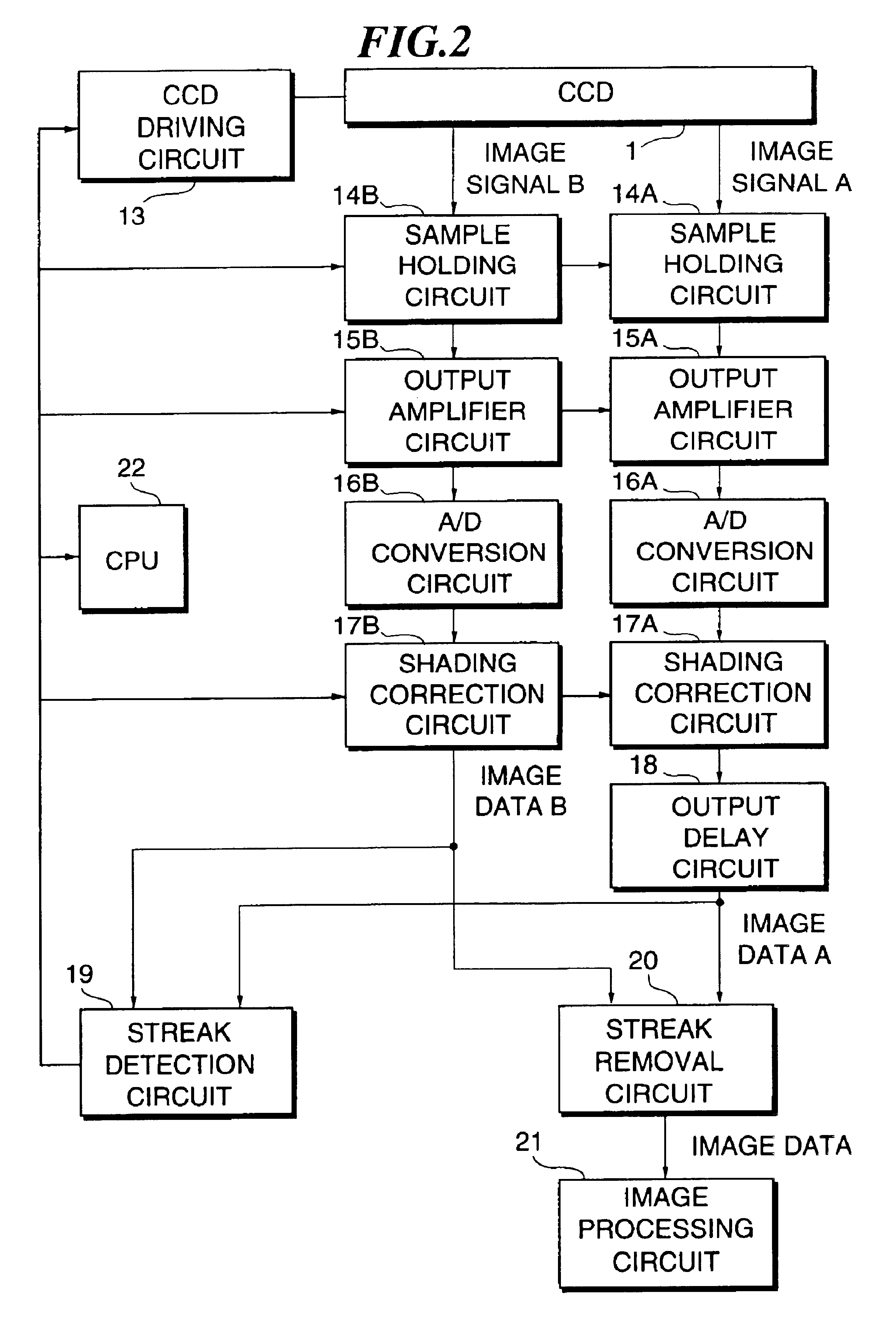
FIG. 1 is a block diagram showing a configuration of an image reader according to a first embodiment of the present invention. In FIG. 1, a reference numeral CCD 1 designates a part for reading an original to be conveyed by an original conveying system shown in FIG. 1. In the present embodiment, this CCD 1 is driven through a driving signal from a CCD driving circuit 13, whereby an original image is read in each of an upstream-side reading position and a downstream-side reading position on a conveying path of the original to output an analog image signal A in the upstream-side reading position and an analog image signal B in the downstream-side reading position.

The configuration of the original conveying system and the configuration of the optical system between each reading position and CCD 1 on the original conveying path are as already described referring to FIG. 1.

On a package for the CCD 1, two rows of line sensors, in each of which N pieces of 7 μm×7 μm phot...

second embodiment

B. Second Embodiment

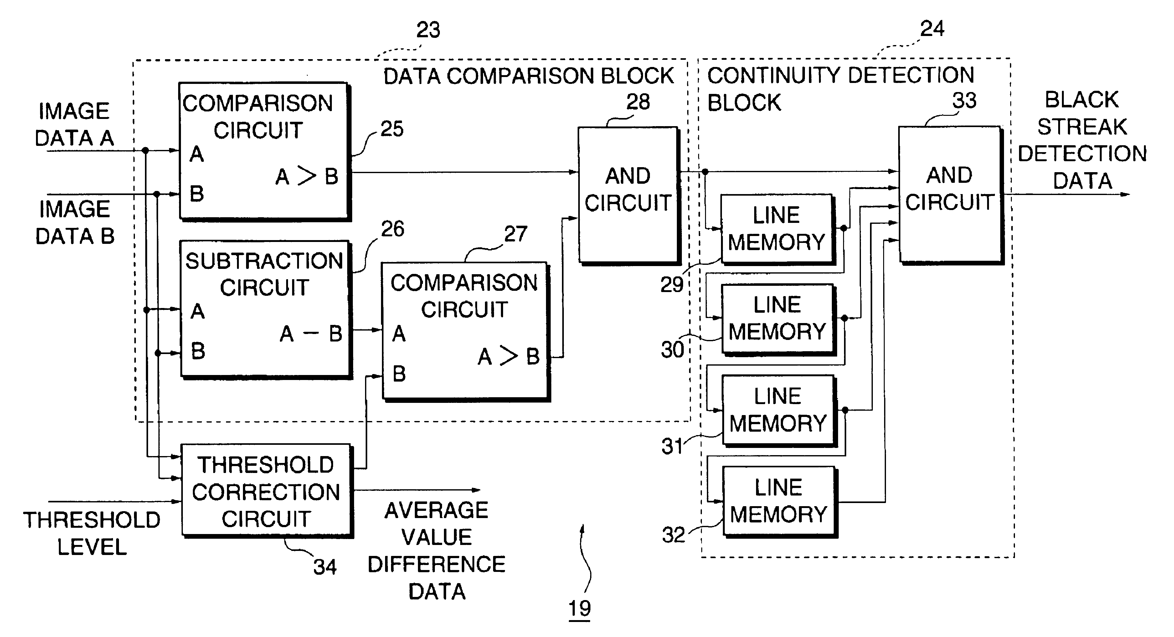
FIG. 8 is a block diagram showing the configuration of an image reader according to a second embodiment of the present invention. In this embodiment, the streak detection circuit 19 and the streak removal circuit 20 are replaced with a streak detection circuit 119 and a streak removal circuit 120 respectively, and a density correction circuit 118 is added. In other respects, the configuration of the present embodiment is quite the same as that of the first embodiment.

The density correction circuit 118 is, as shown in FIG. 9, constructed of average value computing circuits 135 and 136, a subtraction circuit 137 and an addition circuit 138. To the average value computing circuits 135 and 136, there are inputted image data pieces A and B corresponding to the same image obtained in the upstream-side reading position and the downstream-side reading position. The average value computing circuit 135 determines an average value for 64 pixels on the image data A. Also, th...


PUM


Abstract

Even if there may exist a difference in reading density between reading positions, there will be provided an image reader capable of accurately detecting and removing streaks-shaped noise caused by the adhesion of dust particles to the reading unit. A CCD reads an original at each reading position, and image data A and B in each reading position are obtained from an output delay circuit and a shading correction circuit. A streak detection circuit judges a difference A−B between each image data through the use of a threshold corrected on the basis of an average density difference between each image data A and B, and outputs black streak detection data in accordance with the judgment result. A streak removal circuit always outputs the image data A, but if black streak detection data is outputted, image data B corrected on the basis of the average density difference is outputted in place of the image data A.

Description

BACKGROUND OF THE INVENTION1. Field of the InventionThe present invention relates to an image reader such as a digital copying machine, a facsimile and a scanner and its image reading method.2. Description of the Prior ArtThere have been provided various types of image readers such as a digital copying machine, a facsimile and a scanner which read an original to be conveyed by a conveying device in a predetermined reading position. In these types of image readers, dust particles or the like may adhere to a reading unit. In such cases, when an image is read, the dust particles are read by the reading unit, and therefore, streaks, which are not in the original image but extend in the slow-scanning direction, appear on an output image or a transmitted image (hereinafter, simply referred to as “output image”) to be obtained from the image reader.As a way of solving this problem, there have been proposed a method of giving processing for preventing dust particles or the like from adherin...

Claims


Application Information

Patent Timeline
IPC IPC(8): G06K15/00H04N1/04H04N1/409
CPCH04N1/4097
Inventor SHIMIZU, KOSUKE
Owner FUJIFILM BUSINESS INNOVATION CORP
Why Eureka
Try Eureka