High damping labyrinth seal with helicoidal and helicoidal-cylindrical mixed pattern

Active Publication Date: 2015-03-26
NUOVO PIGNONE TECH SRL
View PDF9 Cites 18 Cited by
  • Summary
  • Abstract
  • Description
  • Claims
  • Application Information

AI Technical Summary

Benefits of technology

[0015]A very important technical feature of the present invention and all its embodiments is the plurality of groves having a helical pattern; it is worth noting that such grooves have not to be confused con swirl brakes, in particular protrusions acting as swirl brake

Problems solved by technology

Abradable labyrinth seals are practically not applicable in high pressure centrifugal compressors because of their high destabilizing effects.
Although small clearances in both statoric and rotoric labyrinth seals can reduce leakage, they also negatively influence rotor stability due to inlet swirl at the entrance to the labyrinth seal a

Method used


Image

  • High damping labyrinth seal with helicoidal and helicoidal-cylindrical mixed pattern
  • High damping labyrinth seal with helicoidal and helicoidal-cylindrical mixed pattern
  • High damping labyrinth seal with helicoidal and helicoidal-cylindrical mixed pattern

Examples


Embodiment Construction

[0028]The following description of the exemplary embodiments refers to the accompanying drawings. The same reference numbers in different drawings identify the same or similar elements. The following detailed description does not limit the invention. Instead, the scope of the invention is defined by the appended claims. The following embodiments are discussed, for simplicity, with regard to the terminology and structure of a centrifugal compressor. However, the embodiments to be discussed next are not limited to such a system, but may be applied (with appropriate adjustments) to other systems of turbomachines such as expanders, pumps and turbines.

[0029]Reference throughout the specification to “one embodiment” or “an embodiment” means that a particular feature, structure, or characteristic described in connection with an embodiment is included in at least one embodiment of the subject matter disclosed. Thus, the appearance of the phrases “in one embodiment” or “in an embodiment” in ...


PUM


Abstract

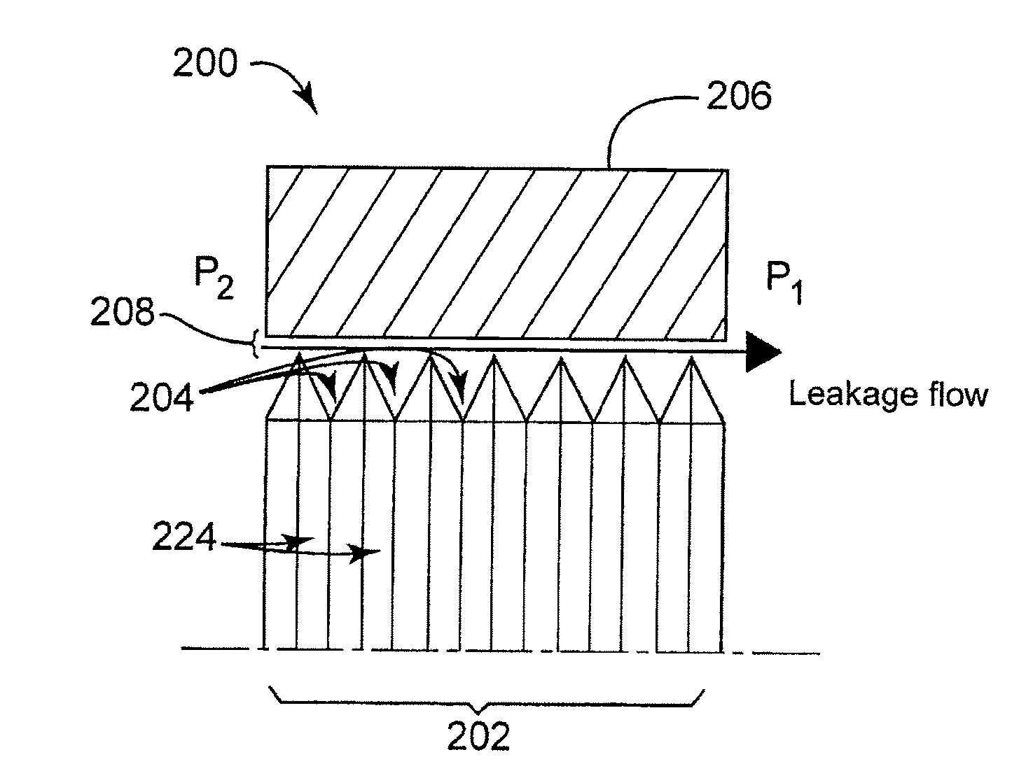
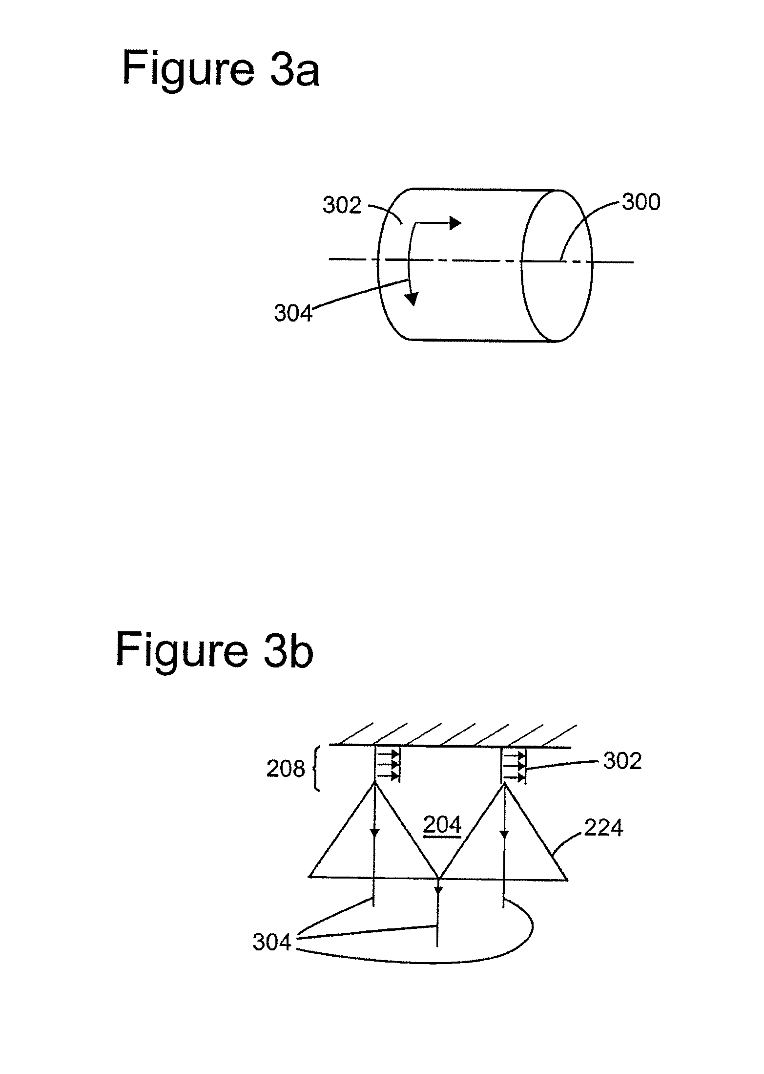
A device for sealing a high pressure region in a turbomachine from a low pressure region; the turbomachine has one or more statoric parts and one or more rotoric parts; the device comprises a labyrinth seal having a first plurality of grooves and a second plurality of grooves; the first plurality of grooves is disposed in a helical pattern and the second plurality of grooves is disposed in a cylindrical pattern; the labyrinth seal is disposed between at least one of the one or more rotoric parts of the turbomachine and at least one of the one or more statoric parts of the turbomachine between the high pressure region and the low pressure region of the turbomachine; the helical pattern has a helix angle less than or equal to 10°, wherein a stabilization effect of the turbomachine is obtained and leakage due to the second plurality of grooves is negligible.

Description

BACKGROUND[0001]Embodiments of the subject matter disclosed herein generally relate to turbomachines, and more particularly, to devices and methods for improving rotordynamics in turbomachines.[0002]Labyrinth seals are commonly used in order to minimize leakages from high pressure regions to low pressure regions in turbomachines such as pumps, centrifugal compressors, and turbines. Labyrinth seals include a number of grooves or teeth that form a tortuous path, or “labyrinth” between a stationary portion, or “stator,” and a rotating portion, or “rotor,” of the turbomachine. Labyrinth seals may be statoric, in which the teeth are formed on the stator, or rotoric, in which the teeth are formed on the rotor. The grooves or teeth of the labyrinth seal and opposing surface impede the flow of fluids from the high pressure region to the low pressure region through the labyrinth seal. However, a space or clearance is necessary between the labyrinth grooves or teeth and an opposing surface to...

Claims


Application Information

Patent Timeline
IPC IPC(8): F01D11/02F01D11/08
CPCF01D11/08F01D11/02F04D29/102F04D29/106F04D29/668F04D29/669F16J15/406F16J15/44F16J15/4472F04D29/10
Inventor RIZZO, EMANUELEPELAGOTTI, ANTONIO
Owner NUOVO PIGNONE TECH SRL
Why Eureka
Try Eureka