Mobile solar power system and method for deploying same

a solar power system and mobile technology, applied in the field of power systems, can solve the problems of insufficient compactness or transportability of prior art systems, inconvenient transportation from one generation site to the next generation site, and insufficient compactness or transportability of solar power generation systems

Inactive Publication Date: 2015-04-02
SOLAROVER
View PDF3 Cites 18 Cited by
  • Summary
  • Abstract
  • Description
  • Claims
  • Application Information

AI Technical Summary

Problems solved by technology

However, solar power generation systems have several drawbacks.
One particularly relevant drawback is that conventional systems are not designed for easy transportation from one generation site to another.
Although various prior art systems have been disclosed which attempt to address this transportation issue, the prior art systems are not sufficiently compact or transportable.
US 2011 / 0057512 A1 do not provide for a sufficiently large deployed footprint from a sufficiently small transport footprint.
Another drawback of conventional mobile power systems is difficulty of deployment once the systems are transported to a specific site.
Such setup is more difficult and time consuming than is desired.

Method used


Image

  • Mobile solar power system and method for deploying same
  • Mobile solar power system and method for deploying same
  • Mobile solar power system and method for deploying same

Examples


Embodiment Construction

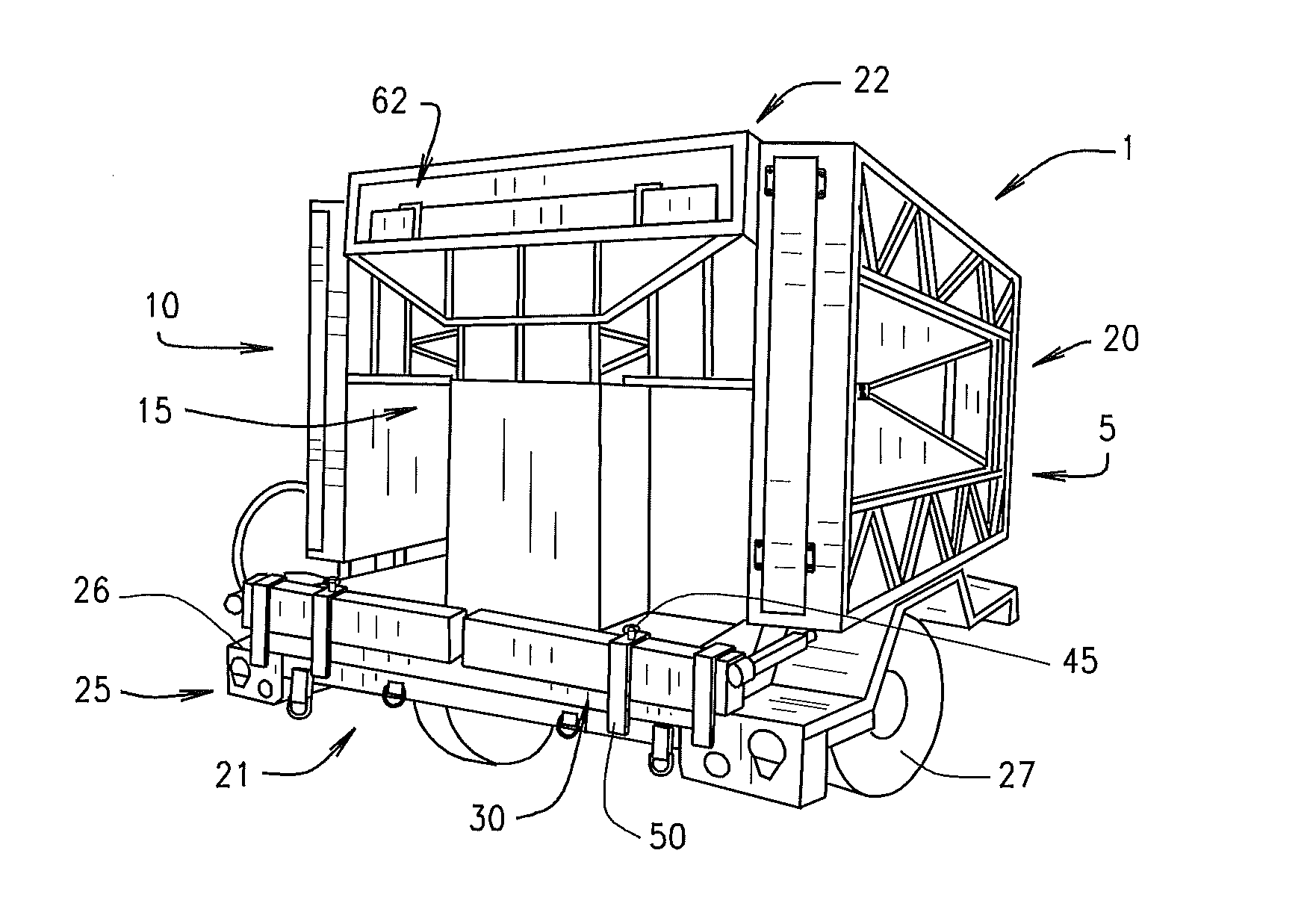
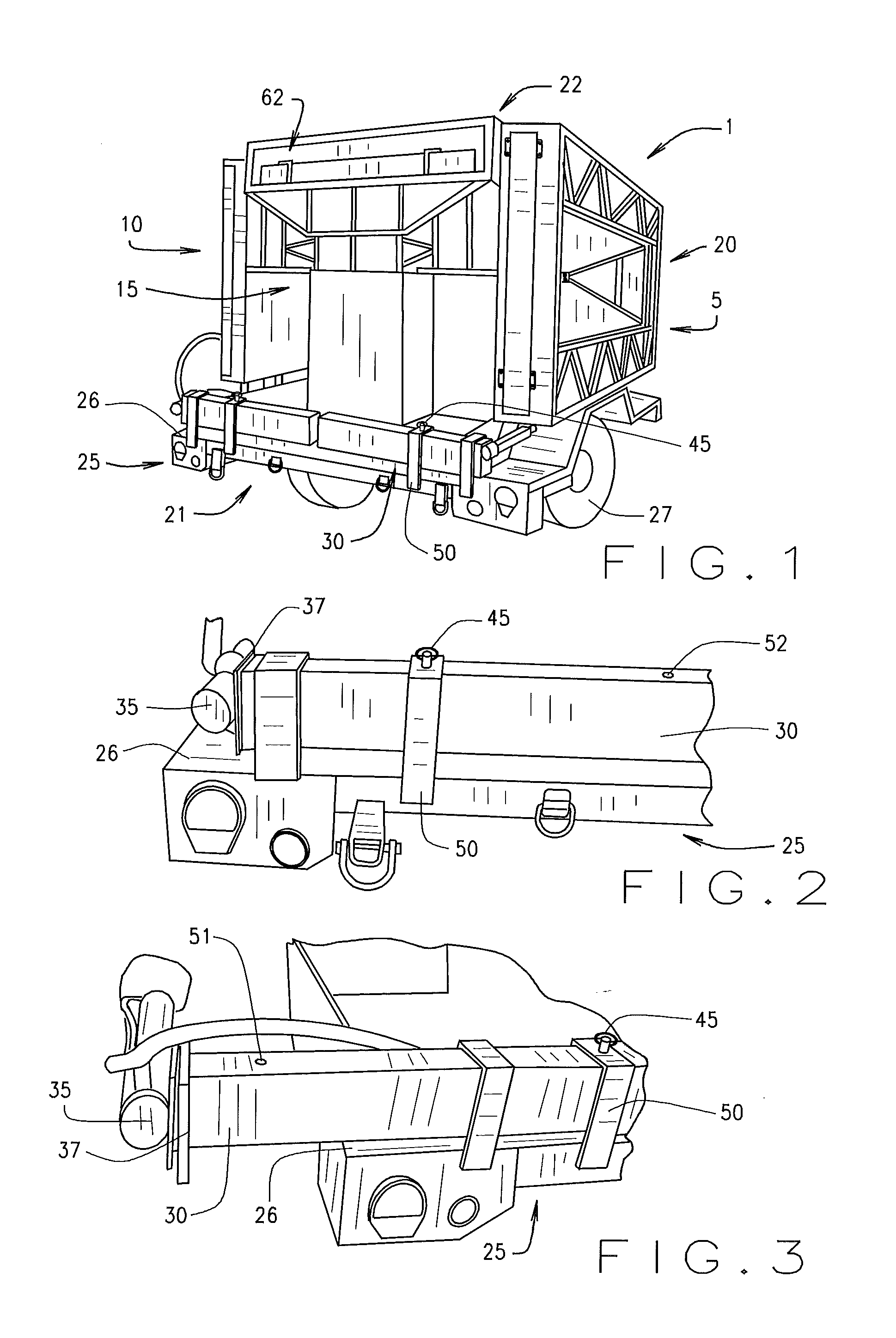
[0043]The following detailed description illustrates the invention by way of example and not by way of limitation. This description will clearly enable one skilled in the art to make and use the invention, and describes several embodiments, adaptations, variations, alternatives and uses of the invention.

[0044]FIG. 1 illustrates a mobile solar power system 1, hereinafter referred to as simply “the power system” or “the unit”). The power system may be constructed so that it may be easily transported in the compact form illustrated in FIG. 1 until it is delivered to a deployment location. The power system 1 may include a right portion 5, a left portion 10, a front portion 15, a rear portion 20, a bottom portion 21 and a top portion 22. The power system is structured and arranged to be transportable by being mounted on a trailer 25, the trailer 25 being adapted to receive and secure the unit, as is known in the art.

[0045]Trailer 25 may be attached to a truck or other towing vehicle to f...


PUM


Abstract

A mobile solar power system provides electricity to various electronic devices needing a source of electricity in remote locations. The mobile solar power system may be transported in a compact form to a remote location by a trailer configured for securely transporting the mobile solar power system. Arrays for containing solar panels may be attached to the mobile solar power system. When a user is ready to deploy the solar panels of the various arrays, the arrays may be slid out from the mobile solar power system and / or unfolded from the mobile solar power system. After the arrays are deployed, the arrays including solar panels may be angled such that the solar panels may be exposed to solar energy which may be subsequently passed through to the various electronic devices needing a source of electricity.

Description

CROSS-REFERENCE TO RELATED APPLICATIONS[0001]The present invention claims the benefit of U.S. Provisional Patent Application No. 61 / 885,823 for MOBILE SOLAR POWER SYSTEM WITH OPTIMIZED DEPLOYED-TO-TRANSPORT RATIO AND METHOD FOR DEPLOYING SAME, filed on Oct. 2, 2013; U.S. Provisional Patent Application No. 61 / 885,801 for SELF-DEPLOYING MOBILE SOLAR POWER SYSTEM AND METHOD FOR DEPLOYING SAME, filed on October 2, 2013; and U.S. Provisional Patent Application No. 61 / 885,783 for MOBILE SOLAR POWER SYSTEM AND METHOD FOR DEPLOYING SAME, filed on October 2, 2013. The present invention incorporates herein by reference the entirety of the U.S. Provisional Patent Applications listed herein above.FIELD OF INVENTION[0002]The present invention relates generally to the field of power systems. More specifically, the present invention relates to a mobile solar power system having a compact, transportable trailer, and which may be quickly and readily deployed in the field.BACKGROUND OF INVENTION[0003...

Claims


Application Information

Patent Timeline
Patent Type & Authority Applications(United States)
IPC IPC(8): H02S10/40H02S30/20H02S20/30
CPCH02S10/40H02S30/20H02S20/30F24S30/20F24S30/425F24S2025/012Y02E10/47Y02E10/50
Inventor SPISAK, JOHN S.
Owner SOLAROVER
Why Eureka
Try Eureka