Image reading apparatus

a technology of image reading and reading apparatus, which is applied in the direction of electrical equipment, pictoral communication, etc., can solve the problems of reducing the adhesion force of the adhesive agent, affecting the effect of photo quality, and affecting the quality of the photo,

Active Publication Date: 2015-04-02
PFU LTD
View PDF1 Cites 5 Cited by
  • Summary
  • Abstract
  • Description
  • Claims
  • Application Information

AI Technical Summary

Benefits of technology

[0011]It is an object of the present invention to at least

Problems solved by technology

Particularly, in the case of a photo album in which photos are fixed with an adhesive agent, there are problems such that the photo is damaged when removing the photo, and that an adhesive force of the adhesive agent decreases due to the removal, which causes difficulty in fixing the photo again on the photo album.
In the ADF scanner, the photo is carried to the image capturing unit by a carriage roller, which results in a problem of damaging the photo.
Similarly, the handy scanner has a problem of damaging the medium because the handy scanner contacts the medium.
Beca

Method used


Image

  • Image reading apparatus
  • Image reading apparatus
  • Image reading apparatus

Examples


first embodiment

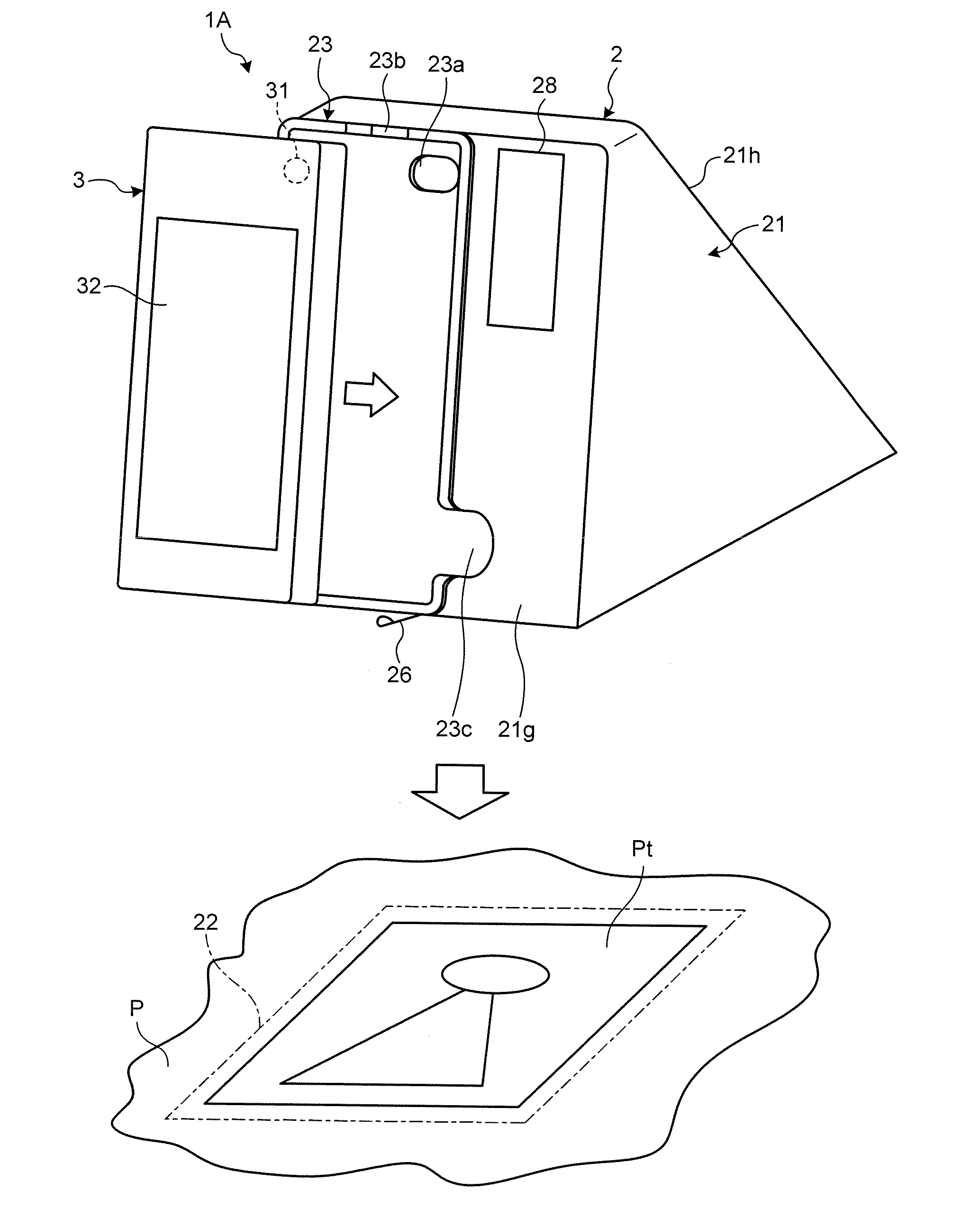
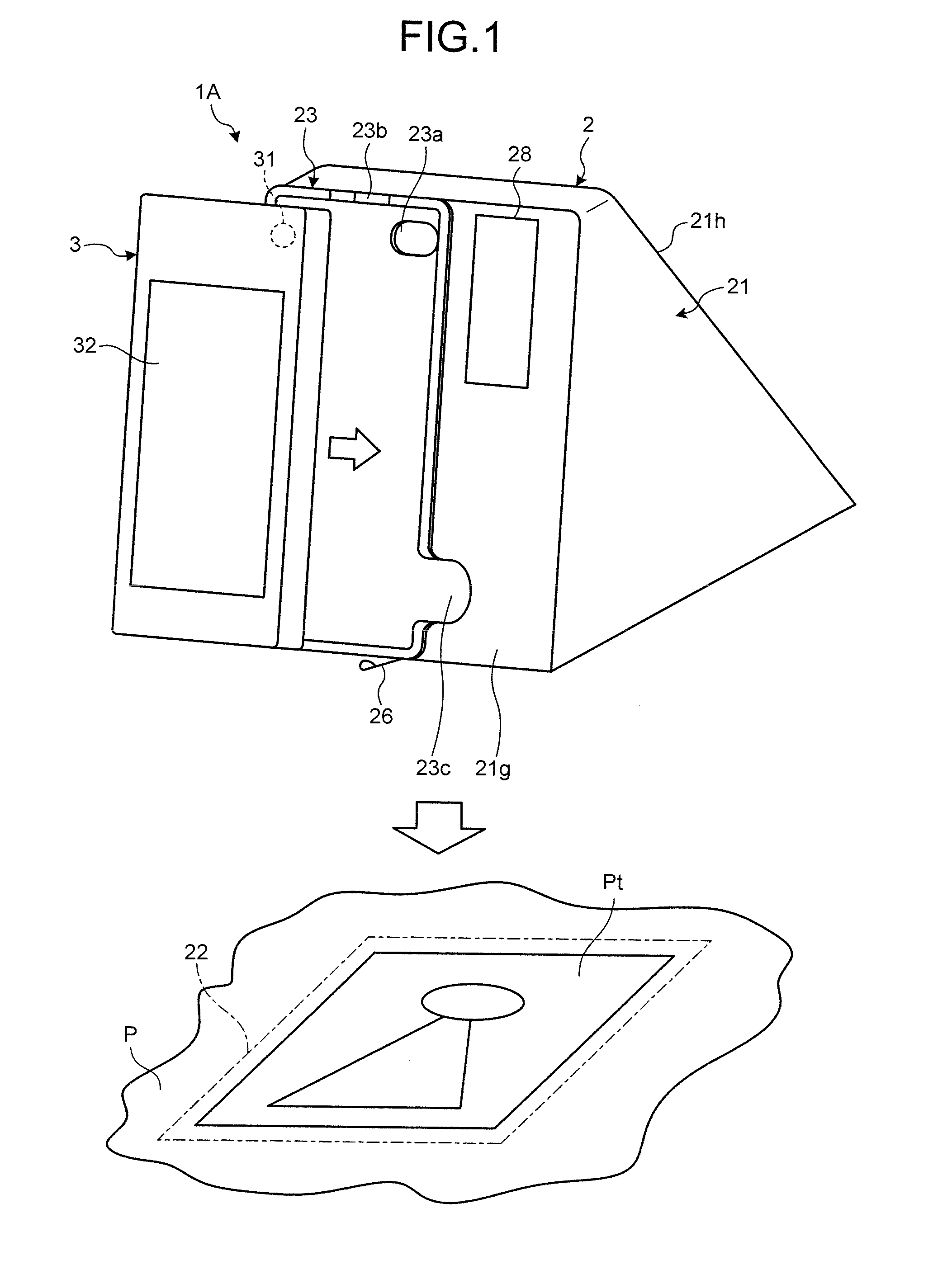
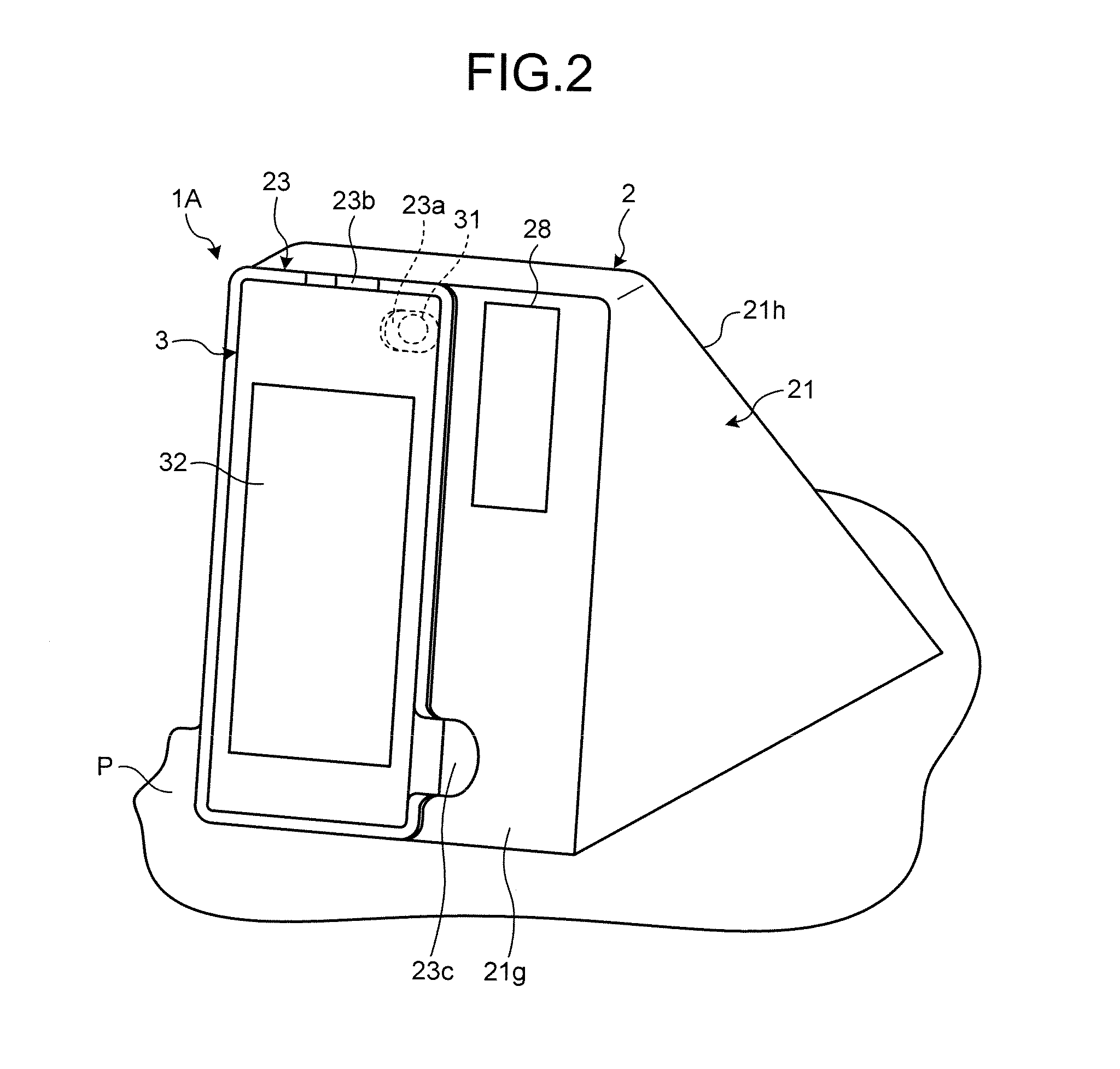
[0032]FIG. 1 is an external view of an image reading apparatus according to a first embodiment. FIG. 2 is a diagram illustrating a state in which the image reading apparatus according to the first embodiment is in use (hereinafter, in-use state). FIG. 3 is a bottom view of a casing. FIG. 4 is a cross sectional view of the image reading apparatus in the in-use state. FIG. 5 is a diagram illustrating main irradiation areas. FIG. 6 is a diagram illustrating a schematic configuration example of the image reading apparatus according to the first embodiment. An image reading apparatus 1A, according to the first embodiment, has a size that can be carried by hand. As illustrated in FIG. 1 and FIG. 2, an image of a medium P is captured by an image capturing unit 31, thereby generating image data corresponding to the medium P. The image reading apparatus 1A in this embodiment regards a photo album, in which silver halide photos or printed photos are compiled, as a medium P, reads a single pho...

second embodiment

[0070]Descriptions will now be made to an image reading apparatus according to a second embodiment. FIG. 11 is an external view of the image reading apparatus according to the second embodiment. FIG. 12 is a diagram illustrating a schematic configuration example of the image reading apparatus according to the second embodiment. An image reading apparatus 1B according to the second embodiment differs from the image reading apparatus 1A according to the first embodiment, in an aspect that a casing 2 (instead of an external device 3) has an image capturing unit 29, as illustrated in FIG. 11 and FIG. 12. The basic configuration of the image reading apparatus 1B is substantially the same as that of the image reading apparatus 1A, and thus the same reference numerals will not be or only simply be described.

[0071]In the casing 2, a holder portion 23 for accommodating the external device 3 is not formed, and so the external device 3 is not attachable to the casing 2. In this embodiment, the...

third embodiment

[0086]Descriptions will now be made to an image reading apparatus according to a third embodiment. FIG. 15 is an external view of the image reading apparatus according to the third embodiment. FIG. 16 is a diagram illustrating a schematic configuration example of the image reading apparatus according to the third embodiment. As illustrated in FIG. 15 and FIG. 16, an image reading apparatus 1C according to the third embodiment differs from the image reading apparatus 1A according to the first embodiment in aspects that it does not have an external device 3 and that a casing 2 has an image capturing unit 29 and a display unit 30. The basic configuration of the image reading apparatus 1C is substantially the same as the basic configuration of the image reading apparatus 1A, and thus the same reference numerals will not be described or only simply be described.

[0087]The casing 2 is different from the casing 2 in the first embodiment. The image capturing unit 29 and the display unit 30 a...


PUM


Abstract

An image reading apparatus includes a casing that blocks ambient light and has an opening portion in a bottom surface, an image capturing unit that captures an image of a medium exposed to an internal portion of the casing in the opening portion, and a plurality of light sources that are arranged on the internal portion of the casing and irradiate light toward the opening portion. The plurality of light sources irradiate light to different areas on a plane in the opening portion.

Description

CROSS-REFERENCE TO RELATED APPLICATIONS[0001]This application is based upon and claims the benefit of priority from Japanese Patent Application No. 2013-205700, filed Sep. 30, 2013, the entire contents of which are incorporated herein by reference.BACKGROUND OF THE INVENTION[0002]1. Field of the Invention[0003]The present invention relates to an image reading apparatus.[0004]2. Description of the Related Art[0005]There are demands for converting a medium, such as a single sheet of photo (hereinafter, single photo), which may be a silver halide photo photographed with a film camera and obtained through development and printing or a printed photo printed based on image data, or a photo album (album) composed of a plurality of photos, into image data to store and manage the image data on a recording medium such as a hard disk or a cloud computing system. Generally, the medium is read to generate the image data, with an image reading apparatus (a flatbed scanner, a scanner with an ADF (...

Claims


Application Information

Patent Timeline
IPC IPC(8): H04N1/028H04N1/00
CPCH04N1/02885H04N1/02895H04N2201/0093H04N1/00538H04N1/00249H04N1/00997
Inventor KASAHARA, YUKIKOBAKO, MASAHIKOTAKAMORI, MASAYA
Owner PFU LTD
Why Eureka
Try Eureka