

Full wrist fusion device
a wrist fusion and wrist technology, applied in the field of full wrist fusion, to achieve the effect of enhancing anti-rotational stability
- Summary
- Abstract
- Description
- Claims
- Application Information
AI Technical Summary
Benefits of technology
Problems solved by technology
Method used
Image

Examples
Embodiment Construction
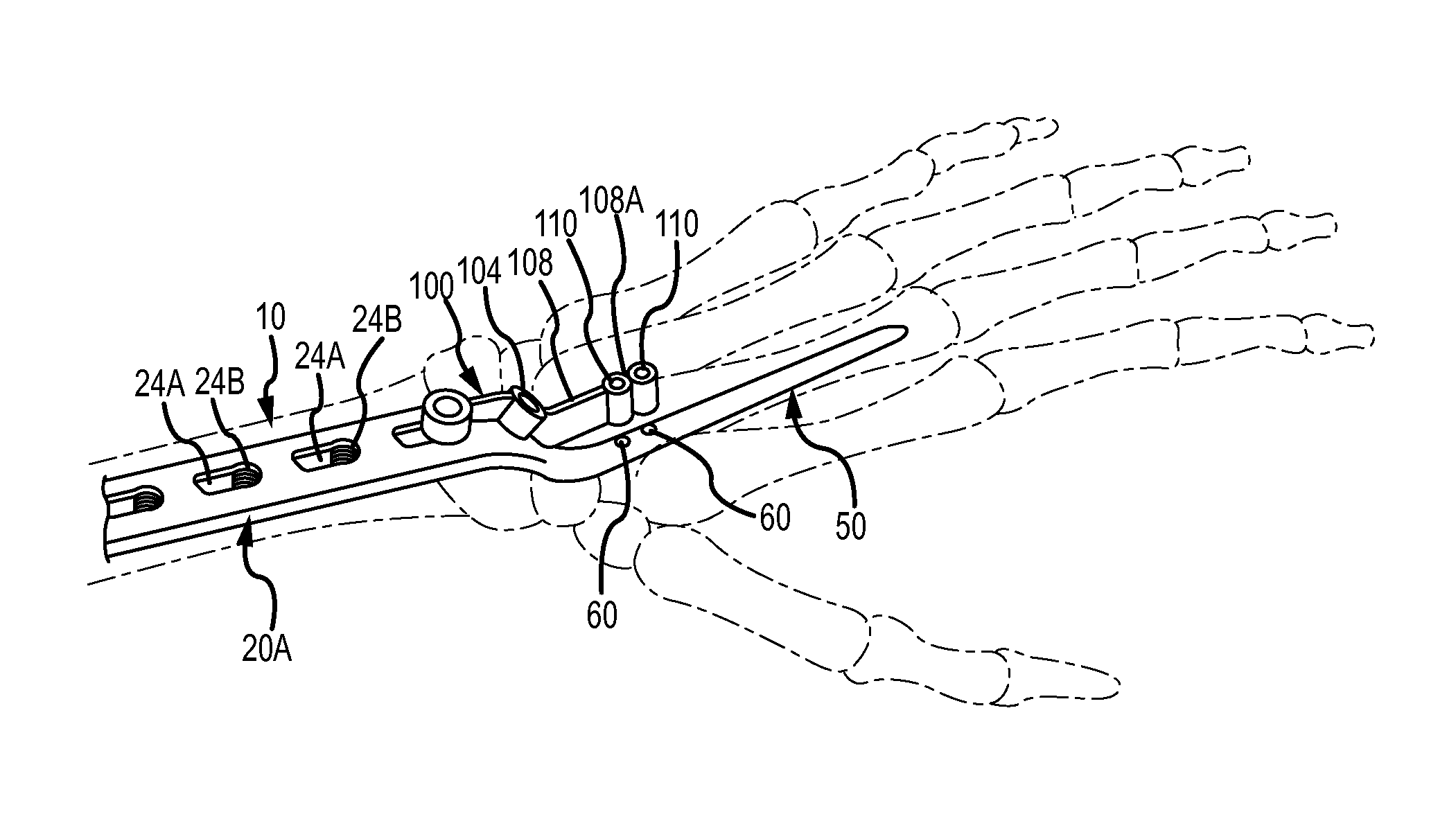
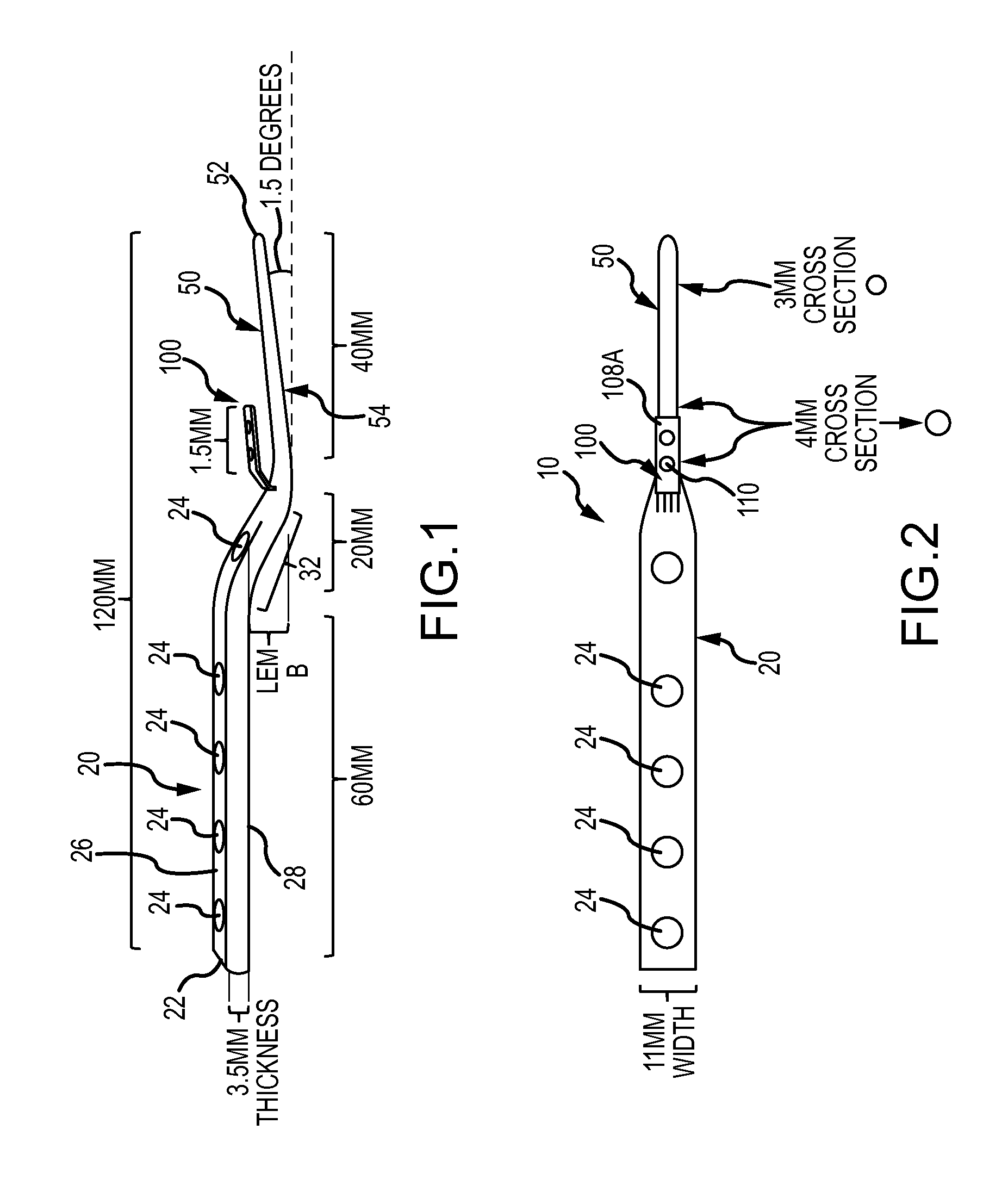
[0016]Turning now to the Figures, where the purpose is to describe preferred embodiments according to the invention and not limit same, FIG. 1 shows a perspective side view of a device 10 according to aspects of the invention. Device 10 has a first section 20 and a second section 50. In one preferred embodiment device 10 has an overall length of between 90 and 150 mm, and is most preferably about 120 mm in length, and is comprised of stainless steel although any suitable material for permanent placement in the body would suffice.
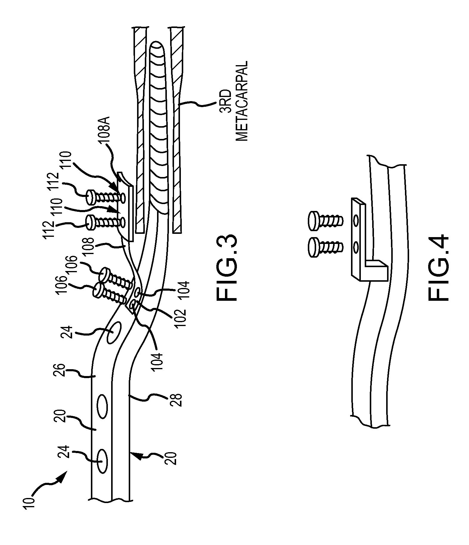
[0017]First section 20 is configured to fit under the skin of the forearm and wrist and connect to the radius bone and one or more carpal bones in the forearm and / or wrist in order to secure section 20. FIGS. 6 and 7 illustrate a device 10 according to the invention fully inserted and attached.
[0018]First section 20 is preferably an elongated plate having a length of 45 mm-75 mm, and most preferably about 60 mm, a thickness of between 3 and 4 mm, and most pr...
PUM
 Abstract
Description
Claims
Application Information