
Method for monitoring components in an exhaust after treatment system, an exhaust after treatment system, and a controller for an exhaust after treatment system

a technology of exhaust after treatment and components, applied in the direction of exhaust treatment electric control, machines/engines, mechanical equipment, etc., can solve the problems of not being able to the temperature downstream of the doc and upstream of the dpf being lower than expected, and the method cannot monitor the catalytic activity of the catalytic dpf. achieve the effect of substantially increasing the cost or complexity of the eats

Active Publication Date: 2015-04-09
VOLVO LASTVAGNAR AB
View PDF6 Cites 5 Cited by
  • Summary
  • Abstract
  • Description
  • Claims
  • Application Information

AI Technical Summary

Benefits of technology

The patent text discusses the need for a multi-component EATS to comply with government regulations related to diesel engine exhaust emissions. The typical EATS includes a DOC, DPF, SCR, and a nozzle for injecting fuel upstream of the DOC. The patent seeks to provide a method for monitoring several components of the EATS simultaneously without increasing costs or complexity. The technical effect is to provide a more efficient and cost-effective solution for monitoring the performance of the EATS in real-time.

Problems solved by technology

However, other problems with the EATS may also be the cause for lower than expected temperatures downstream of the DOC.
For example, a clogged AHI nozzle will also result in temperatures downstream of the DOC and upstream of the DPF being lower than expected.
Also, the method can not monitor the catalytic activity of a catalyzed DPF, which is also critical for controlling NMHC emissions and providing appropriate NO2 / NOx ratio to a downstream SCR for optimal SCR NOx conversion efficiency.
While it is possible to determine that the AHI nozzle is clogged by use of a flow meter in the AHI line, this solution adds substantial cost and complexity to the EATS and its control system.

Method used


Image

  • Method for monitoring components in an exhaust after treatment system, an exhaust after treatment system, and a controller for an exhaust after treatment system
  • Method for monitoring components in an exhaust after treatment system, an exhaust after treatment system, and a controller for an exhaust after treatment system
  • Method for monitoring components in an exhaust after treatment system, an exhaust after treatment system, and a controller for an exhaust after treatment system

Examples


Embodiment Construction

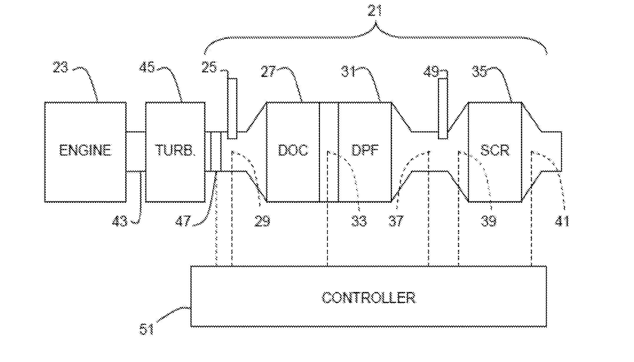
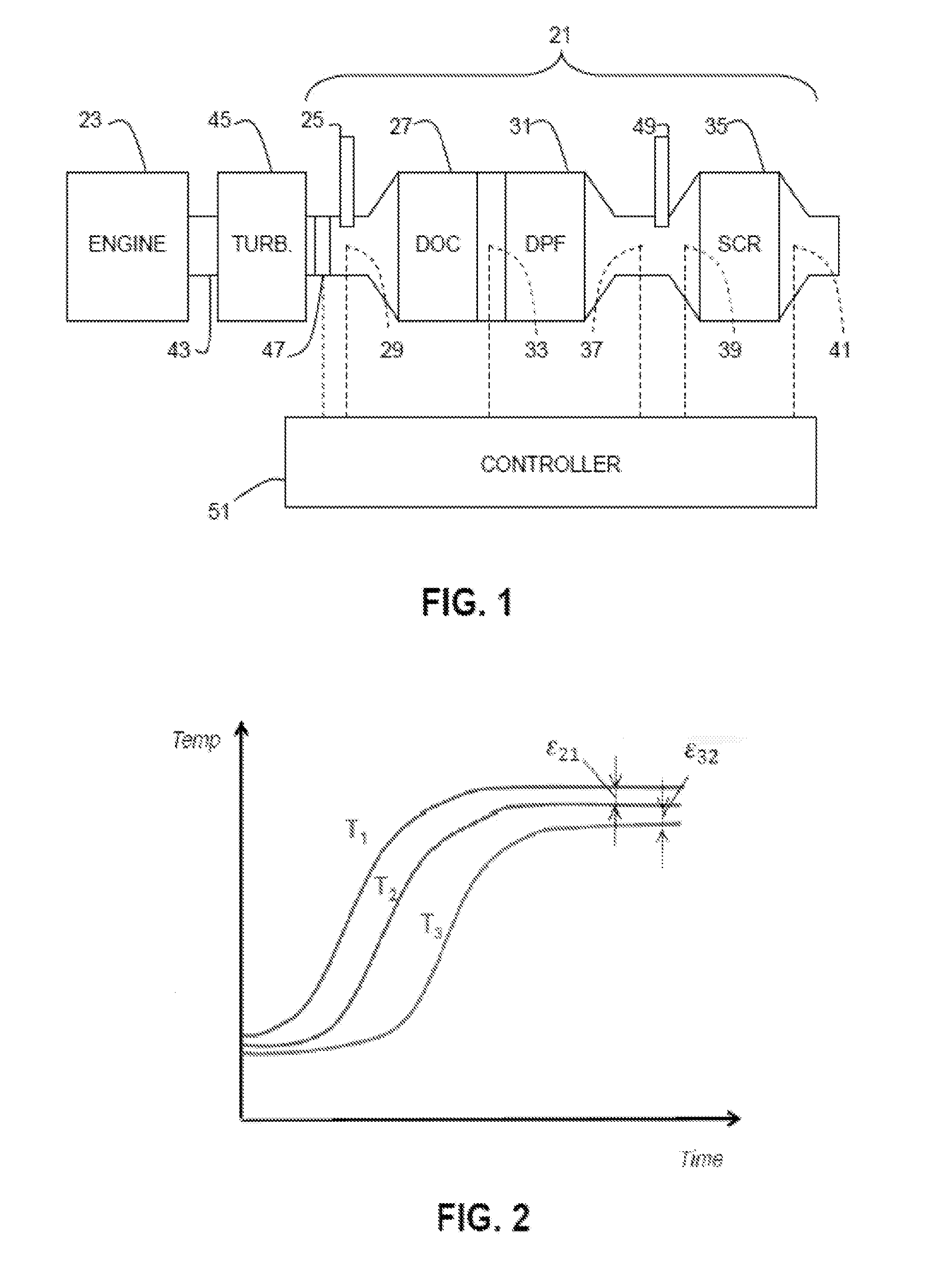
[0013]FIG. 1 shows an exhaust after treatment system (EATS) 21 for a diesel engine 23. The EATS 21 comprises an AHI nozzle 25, a diesel oxidation catalyst (DOC) 27 downstream from the AHI nozzle, a first temperature sensor 29 upstream of the DOC, a diesel particulate filter (DPF) 31 downstream of the DOC, a second temperature sensor 33 downstream of the DOC and upstream of the DPF, a selective catalytic reduction catalyst system (SCR) 35 downstream of the DPF, a third temperature sensor 37 downstream of the DPF and upstream of the SCR, a first NOX sensor 39 upstream of the SCR, and a second NOX sensor 41 downstream of the SCR. A conduit 43 upstream of the DOC and connecting the EATS to the engine 23 typically includes a turbine 45 of a turbocharger and an arrangement 47, such as an orifice and flow meter for measuring, or control logic for calculating exhaust mass flow. A nozzle 49 connected to a source of DEF (not shown) is typically provided upstream of the SCR 35 and downstream o...


PUM


Abstract

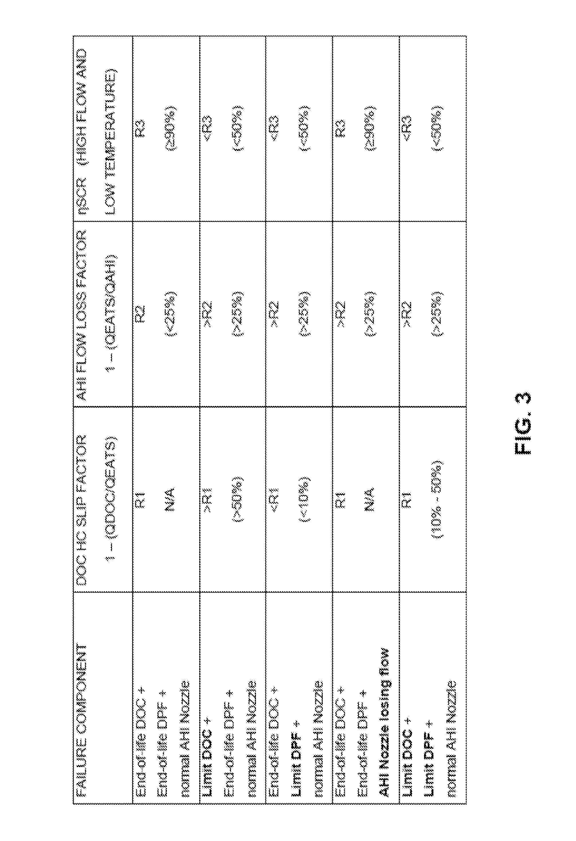
Components in an exhaust after treatment system (EATS) for a diesel engine are monitored by measuring heat released (QDOC) across a diesel oxidation catalyst (DOC) and heat released (QEATS) across the DOC and a diesel particulate filter (DPF) during an A Hi injection event, by calculating heat input from AHI fuel (QAHI) during performance of the AH I injection event with a fully functioning AHI nozzle, and by measuring NOX conversion efficiency (nSCR) from NOX to N2 by a selective catalytic reduction system (SCR) at a condition where a SCR is sensitive to feeding gas compositions while AHI is not in use. Malfunctioning components are identified using these measurements and calculations.

Description

BACKGROUND AND SUMMARY[0001]The present invention relates generally to exhaust after treatment systems (EATS) and, more particularly, to methods and equipment for monitoring components in an EATS.[0002]Government regulations impose strict limits for diesel engine exhaust with regard to, among other things, particulate and NOX emissions. Compliance with these regulations requires a multi-component EATS. A typical EATS will include a diesel oxidation catalyst (DOC), a diesel particulate filter (DPF), and a selective catalytic reduction catalyst system (SCR), as well as an AHI nozzle (also known as a “seventh injector”) for injecting fuel upstream of the DOC to facilitate heating of the EATS and regeneration of the DPF.[0003]To ensure proper functioning of the DOC, it is known to monitor temperature downstream of the DOC and upstream of the DPF to diagnose a malfunctioning DOGC. If temperature is lower than expected, that may indicate a malfunctioning DOC. However, other problems with ...

Claims


Application Information

Patent Timeline
Patent Type & Authority Applications(United States)
IPC IPC(8): F01N11/00F01N3/20F01N3/021
CPCF01N11/002F01N3/2066F01N3/021F01N3/035F01N3/103F01N3/106F01N2550/02F01N2550/04F01N2550/05F01N2560/026F01N2560/06F01N2560/14F01N2900/1618F01N2900/1621F01N2900/1812F01N13/009F01N13/0097Y02T10/12Y02T10/40F01N3/00F01N11/00
Inventor DONG, QUNLONGTAL, CHUN
Owner VOLVO LASTVAGNAR AB
Learn More