Corrugated fin and method for producing it

Inactive Publication Date: 2015-04-09
MAHLE INT GMBH
View PDF5 Cites 6 Cited by
  • Summary
  • Abstract
  • Description
  • Claims
  • Application Information

AI Technical Summary

Benefits of technology

[0008]It is therefore an object of the present invention to provide a corrugated fin and a heat exchanger having a cor

Problems solved by technology

In these corrugated fins with parallel fin surfaces, the possibility of introducing additional turbulence-generating elements in the

Method used


Image

  • Corrugated fin and method for producing it
  • Corrugated fin and method for producing it
  • Corrugated fin and method for producing it

Examples


Example

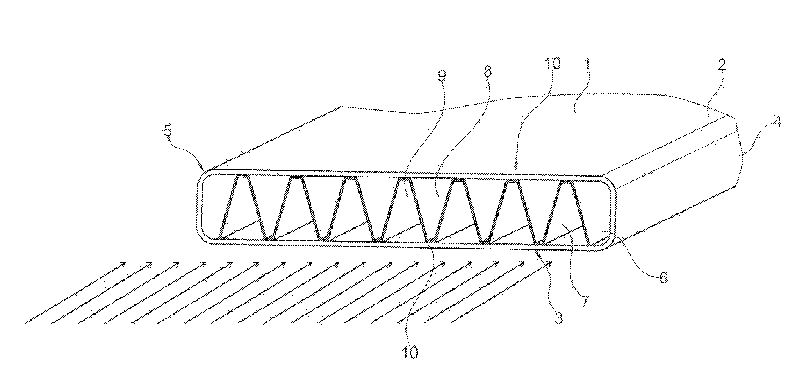
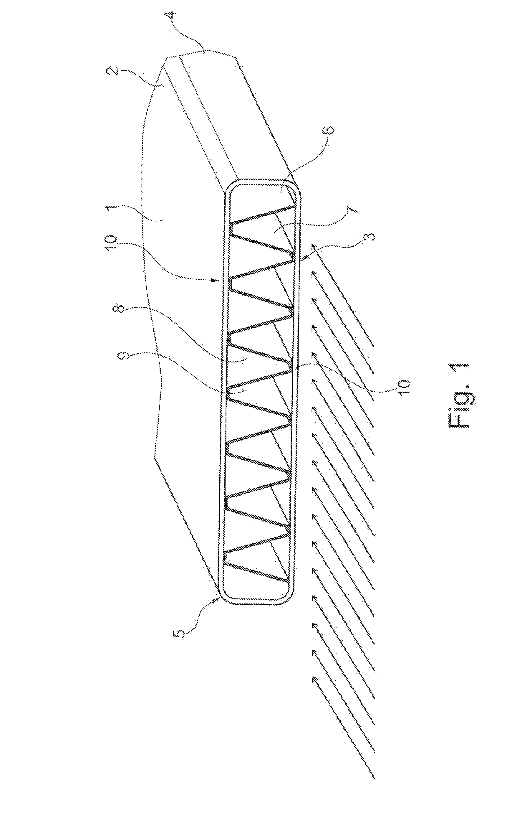
[0061]FIG. 1 shows a tube 1, which is designed as a fluid channel of a heat exchanger, whereby the tube has two wide side surfaces 2, 3 and two narrow side surfaces 4, 5, which lie opposite to each other and define an interior space 6, which is suitable for throughflow for a medium. A corrugated fin 7, formed by fin surfaces 8, 9, each of which is connected together by fin arches 10, is arranged in the interior of tube 1. In this case, fin arches 10 each lie against a side surface 2, 3 of the tube. Fin arches 10 can preferably be soldered to the side surfaces. They can also be applied merely mechanically.

[0062]In a further exemplary embodiment, corrugated fin 7 can also be arranged between two tubes, whereby fin arches 10 are each in contact with a side surface of an adjacent tube or connected thereto.

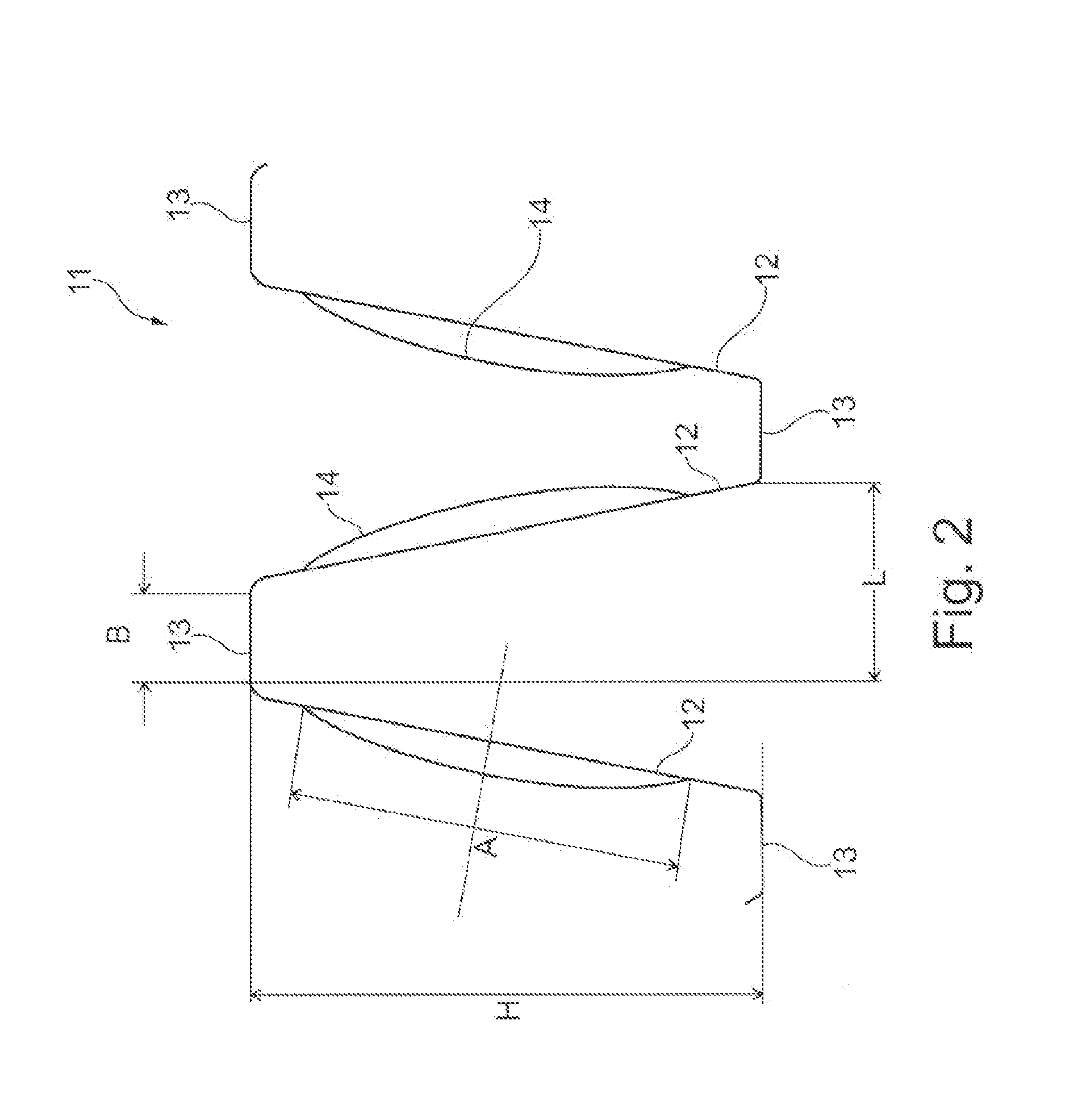
[0063]FIG. 2 shows a section of a corrugated fin 11 in section, whereby the corrugated fin has fin surfaces 12 and fin arches 13 connecting fin surfaces 12, whereby fin surfaces 12 are...


PUM

PropertyMeasurementUnit
Fractionaaaaaaaaaa
Fractionaaaaaaaaaa
Fractionaaaaaaaaaa

Abstract

A corrugated fin, in particular for a heat exchanger, having a substantially corrugated design, having a plurality of fin surfaces, wherein adjoining fin surfaces are connected to one another by means of a fin arch in such a way that a medium can flow through an intermediate space between adjoining fin surfaces, wherein the fin surfaces are arranged at an angle with respect to one another perpendicularly with respect to a throughflow direction for the medium, wherein the fin surface has at least one bulge which protrudes out of the plane of the fin surface, wherein the extent of the bulge in a direction perpendicularly with respect to the air throughflow direction is smaller than the extent of the fin surface in said direction.

Description

[0001]This nonprovisional application is a continuation of International Application No. PCT / EP2013 / 057587, which was filed on Apr. 11, 2013, and which claims priority to German Patent Application No. DE 10 2012 205 916.4, which was filed in Germany on Apr. 11, 2012, and which are both herein incorporated by reference.BACKGROUND OF THE INVENTION[0002]1. Field of the Invention[0003]The present invention relates to a corrugated fin and to a method for the production thereof and to a heat exchanger having such a corrugated fin.[0004]2. Description of the Background Art[0005]Corrugated fins are known in the conventional art for use in heat exchangers to improve the heat transfer. In this regard, corrugated fins are known, for example, for the air-side heat transfer, which are arranged substantially wave-shaped or zigzag-shaped folded back and forth between lateral sides of tubes, so that a medium can flow in the intermediate spaces of the fin. In this regard, corrugated fins have become...

Claims


Application Information

Patent Timeline
IPC IPC(8): F28F3/02B23P15/26B21D13/04
CPCF28F3/02B23P15/26B21D13/04F28F1/126Y10T29/4935
Inventor AGNER, CAROLINHALLER, BJOERNKILIAN, JONASRUCKWIED, JENSSCHMIDT, FLORIANPANTOW, EBERHARDSCHLEIER, GERD
Owner MAHLE INT GMBH
Why Eureka
Try Eureka