

Wide angle optical lens system
a wide angle, optical lens technology, applied in the field of wide angle optical lens systems, can solve the problems of large distortion, inapplicability to mobile devices, and the total track length of these optical lens systems is also too long, and achieves the effect of wide field of view and high resolution
- Summary
- Abstract
- Description
- Claims
- Application Information
AI Technical Summary
Benefits of technology
Problems solved by technology
Method used
Image

Examples
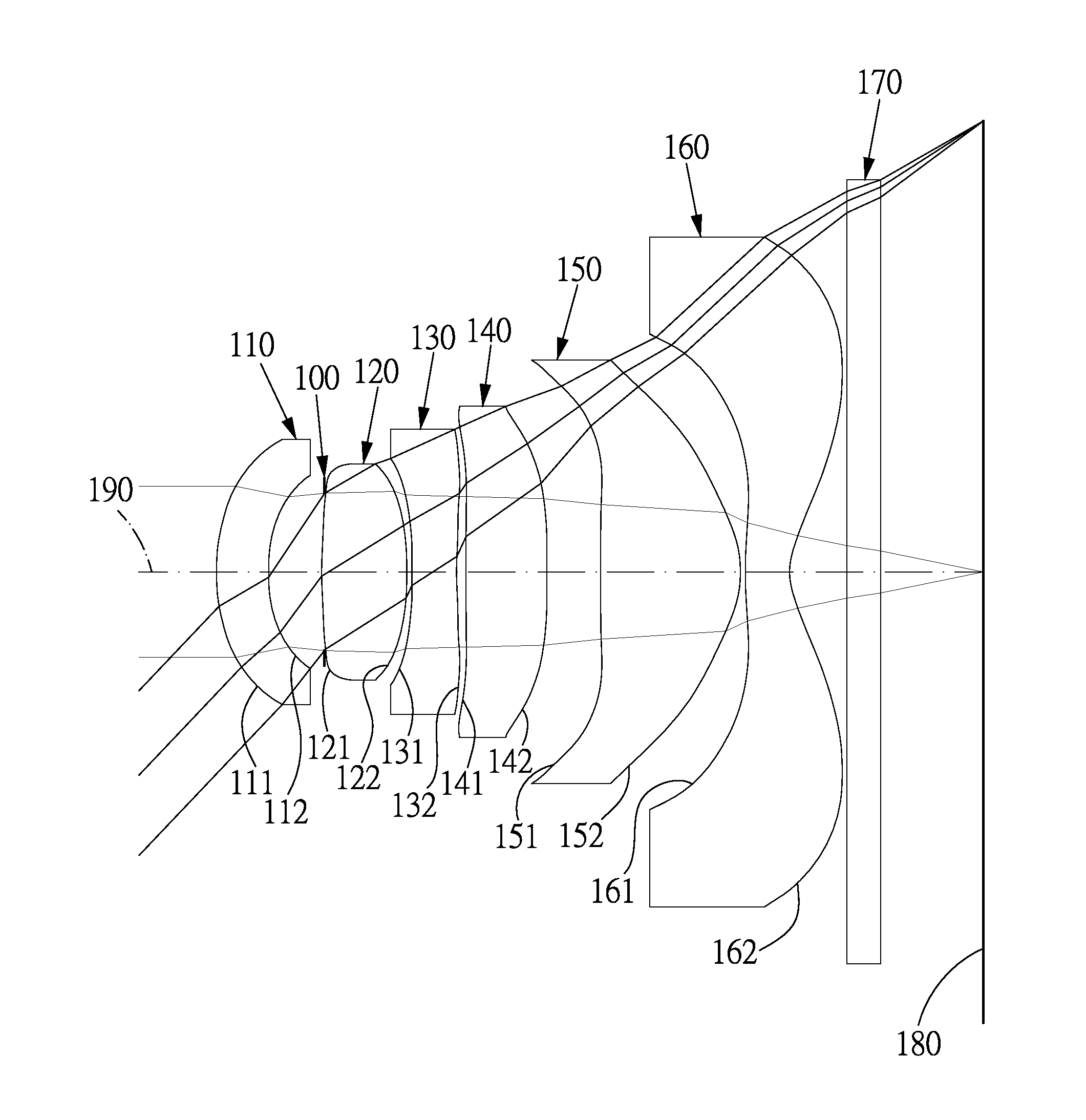
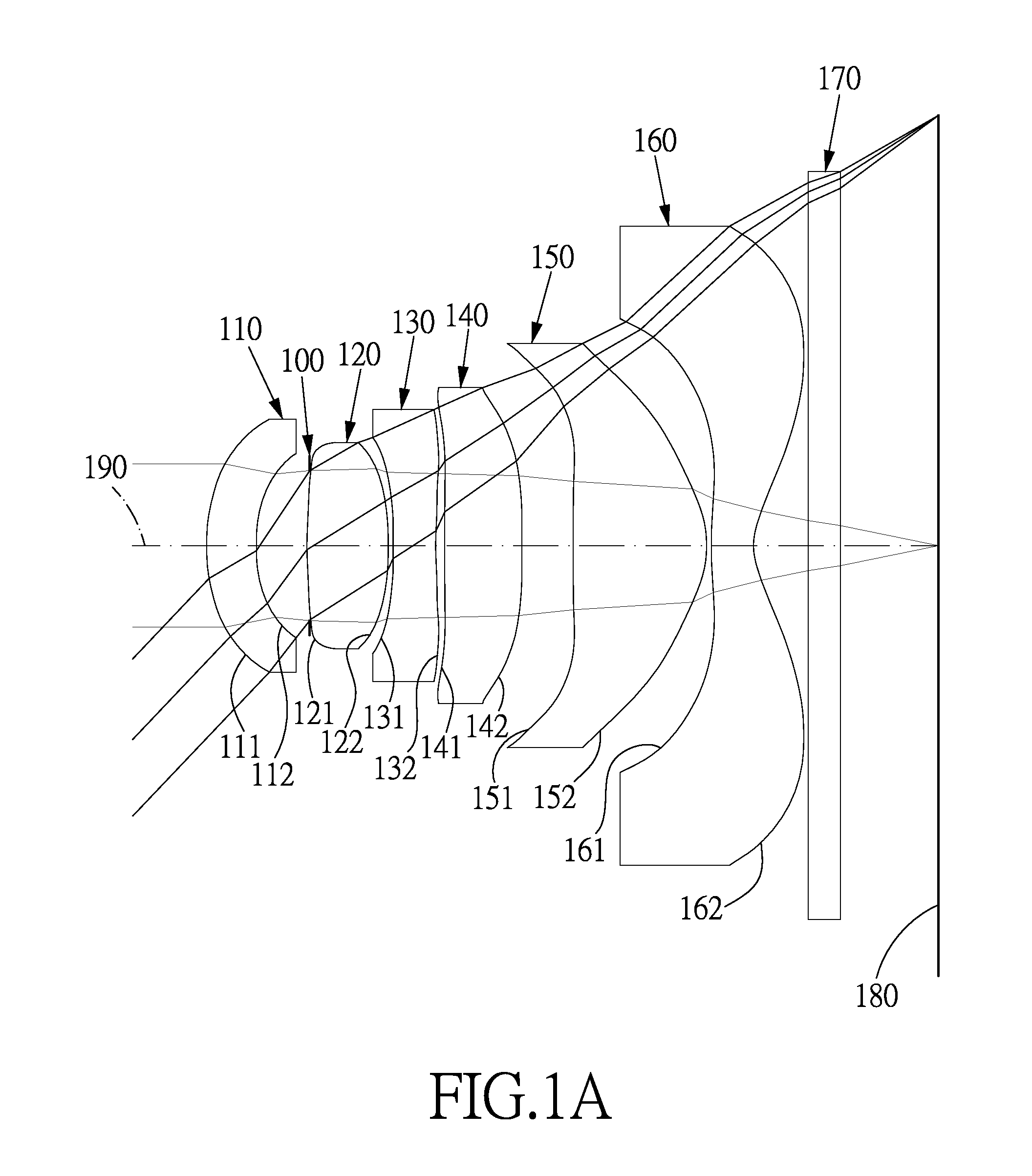
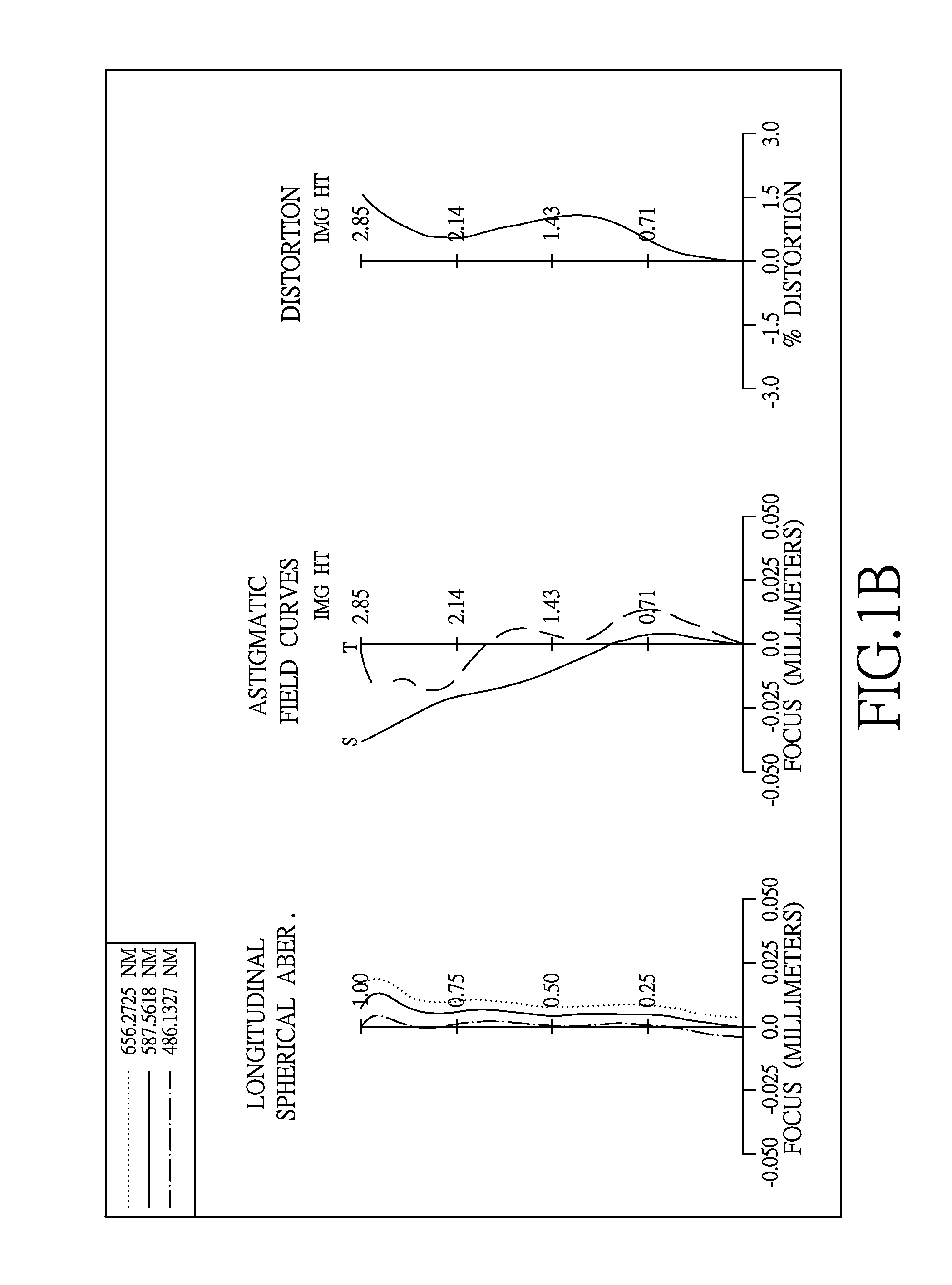
first embodiment
[0068]The equation for the aspheric surface profiles of the first embodiment is expressed as follows:
z(h)=ch21+1-(1+k)c2h2+A4h4+A6h6+A8h8+A10h10+A12h12+A14h14+…
[0069]z represents the distance of a point on the aspheric surface at a height h from the optical axis 190 relative to a plane perpendicular to the optical axis at the vertex of the aspheric surface;
[0070]c is a paraxial curvature equal to 1 / R (R: a paraxial radius of curvature);
[0071]h represents a vertical distance from the point on the curve of the aspheric surface to the optical axis 190;
[0072]k represents the conic constant;
[0073]A4, A6, A8, A10, A12, A14 . . . : represent the high-order aspheric coefficients.
[0074]In the first embodiment of the present wide angle optical lens system, the focal length of the wide angle optical lens system is f, the f-number of the wide angle optical lens system is Fno, half of the maximal field of view of the wide angle optical lens system is HFOV, and the following conditions are satisf...
second embodiment
[0098]The detailed optical data of the second embodiment is shown in Table 3 and the aspheric surface data is shown in Table 4 below.
TABLE 3(Embodiment 2)f(focal length) = 2.46 mm, Fno = 2.4, HFOV = 49.2 deg.FocalSurfaceCurvature RadiusThicknessMaterialindexAbbe #length0ObjectPlaneInfinity1Lens 11.3988(ASP)0.28Plastic1.54655.9−4.521.2361(ASP)0.353AperturePlane 0.013stop4Lens 210.3799(ASP) 0.52Plastic1.54655.92.02925−1.9143(ASP) 0.036Lens 3−4.4116(ASP) 0.28Plastic1.63623.2−4.4921711.3906(ASP) 0.148Lens 43.1259(ASP)0.28Plastic1.54655.97.922292.5187(ASP)0.2310Lens 5−20.6171(ASP) 0.96Plastic1.54655.91.580711−0.7760(ASP) 0.0312Lens 61.5890(ASP)0.47Plastic1.58430.0−1.7981130.6152(ASP)0.4014IR-filterPlane0.21Glass1.51764.0—15Plane0.6516ImagePlane—
TABLE 4Aspheric CoefficientsSurface #124567K =−5.2265−6.720813.38505.3475−90.000027.4239A4 =3.8608E−017.2389E−01−9.7878E−02−3.0263E−01−4.8585E−01−1.6204E−01A6 =−3.8119E−02 −9.4475E−02 1.2449E+00 4.9794E−01 6.0193E−01 9.1200E−02A8 =1.8259E−011.997...
third embodiment
[0109]The detailed optical data of the third embodiment is shown in Table 5 and the aspheric surface data is shown in Table 6 below.
TABLE 5(Embodiment 3)f(focal length) = 2.74 mm, Fno = 2.4, HFOV = 46.2 deg.FocalSurfaceCurvature RadiusThicknessMaterialindexAbbe #length0ObjectPlaneInfinity1Lens 1−7.7204(ASP) 0.28Plastic1.60726.6−49.999723.6688(ASP)0.293AperturePlane−0.136stop4Lens 21.2991(ASP)0.49Plastic1.54655.92.99485−6.8936(ASP) 0.256Lens 310.8587(ASP) 0.28Plastic1.63323.6−4.960772.2350(ASP)0.148Lens 44.8292(ASP)0.42Plastic1.54655.9−28.29289−41.5649(ASP) 0.3110Lens 5−2.2794(ASP) 0.76Plastic1.58230.01.446911−0.7021(ASP) 0.0312Lens 62.3279(ASP)0.50Plastic1.60726.6−2.0229130.6693(ASP)0.3814IR-filterPlane0.21Glass1.51764.0—15Plane0.6516ImagePlane—
TABLE 6Aspheric CoefficientsSurface #124567K =−4.7294−61.86280.352720.3170−83.1597−15.2712A4 =−4.4564E−02−3.4192E−02−1.3658E−01−1.0886E−02−3.1244E−01−1.1179E−01A6 = 4.2786E−02−4.4644E−03 1.3271E−01−1.8351E−02 7.2421E−02 8.6561E−02A8 =−6.3096E...
PUM
 Abstract
Description
Claims
Application Information