X-ray optical component device and x-ray analyzer

a technology of optical components and analyzers, applied in the direction of instruments, liquid/fluent solid measurements, nuclear engineering, etc., can solve the problems of motor control circuits that are also damaged, the output shaft of the motor to rotate, etc., to prevent unwanted changes in position and prevent adverse effects

Active Publication Date: 2015-04-09
RIGAKU CORP
View PDF0 Cites 7 Cited by
  • Summary
  • Abstract
  • Description
  • Claims
  • Application Information

AI Technical Summary

Benefits of technology

The X-ray optical component device described in this patent prevents damage and unwanted movement of the X-ray optical component by stopping the supply of electric power to the motor when the connector is detached. This is done by controlling the power feed path rather than interrupting the electric power supply wire before the emergence of a surge current from the motor. This prevents damage to internal circuits and ensures the X-ray optical component operates safely and efficiently.

Problems solved by technology

When the distal ends of the plurality of pins and the plurality of terminals are at the same position as described above in a case in which a motor is provided inside the X-ray optical component unit in the manner described above, when the connector is detached in a state in which the motor is being controlled to a stationary state, a problem occurs whereby a counter-electromotive force and a surge current (i.e., a current that fluctuates sharply in a short time) cause an output shaft of the motor to rotate, despite the need for the motor to be stopped.
In some cases, a control circuit controlling the motor is also damaged.
However, Patent Citation 2 does not go so far as to relate and apply the technique of hot swapping to operation of a motor when the motor is provided in a constituent unit.
However, Patent Citation 3 also does not go so far as to relate and apply the technique of hot swapping to operation of a motor when the motor is provided in a constituent unit.
However, Patent Citation 4 also does not go so far as to relate and apply the technique of hot swapping to operation of a motor when the motor is provided in a constituent unit.

Method used


Image

  • X-ray optical component device and x-ray analyzer
  • X-ray optical component device and x-ray analyzer
  • X-ray optical component device and x-ray analyzer

Examples


Embodiment Construction

[0036]The X-ray optical component device and X-ray analyzer according to the present invention are described below on the basis of embodiments. The present invention is, of course, not limited to these embodiments. In the drawing accompanying the present specification, constituent elements are sometimes shown at a scale that is different from the actual scale thereof in order to facilitate understanding of characteristic portions.

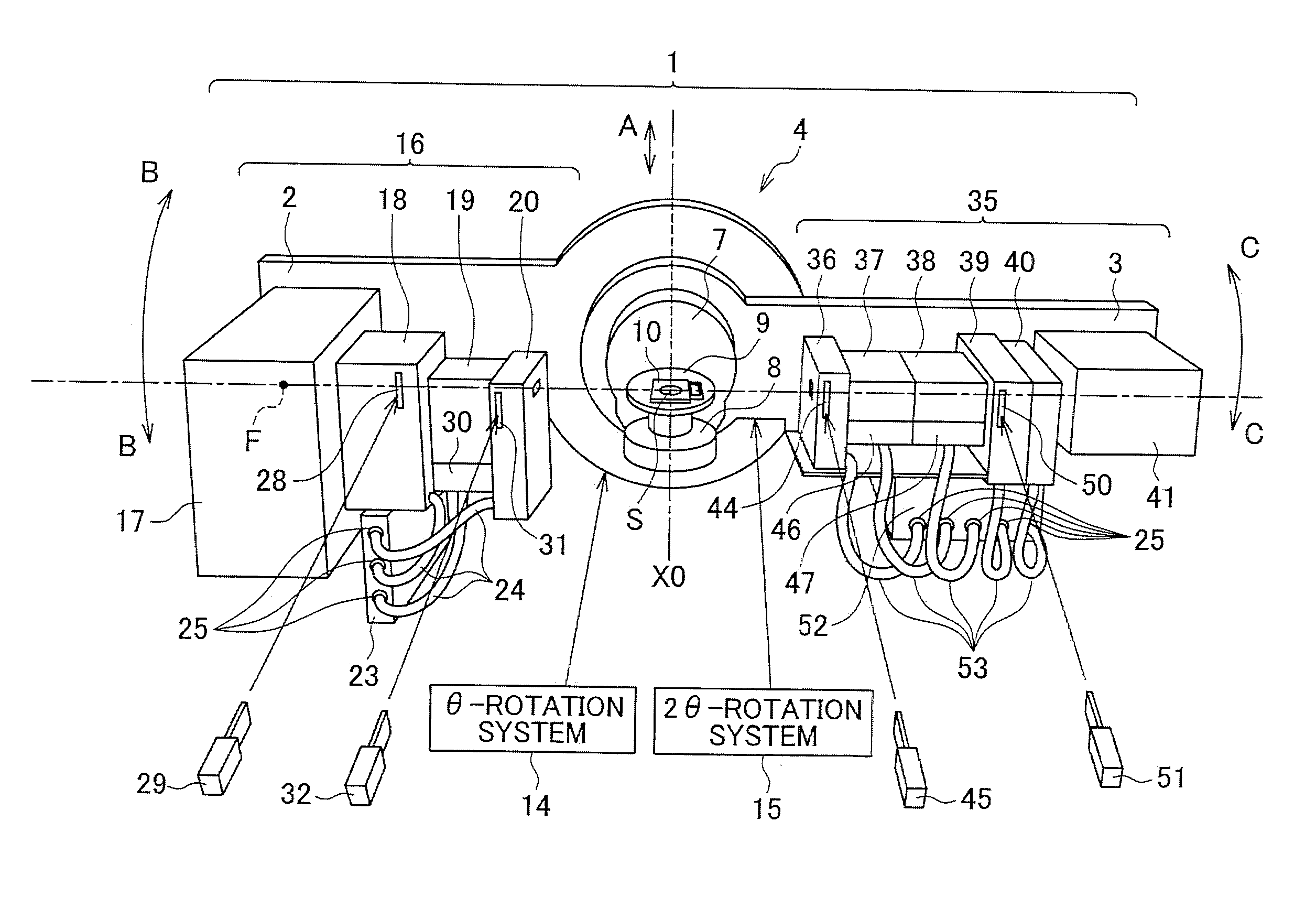
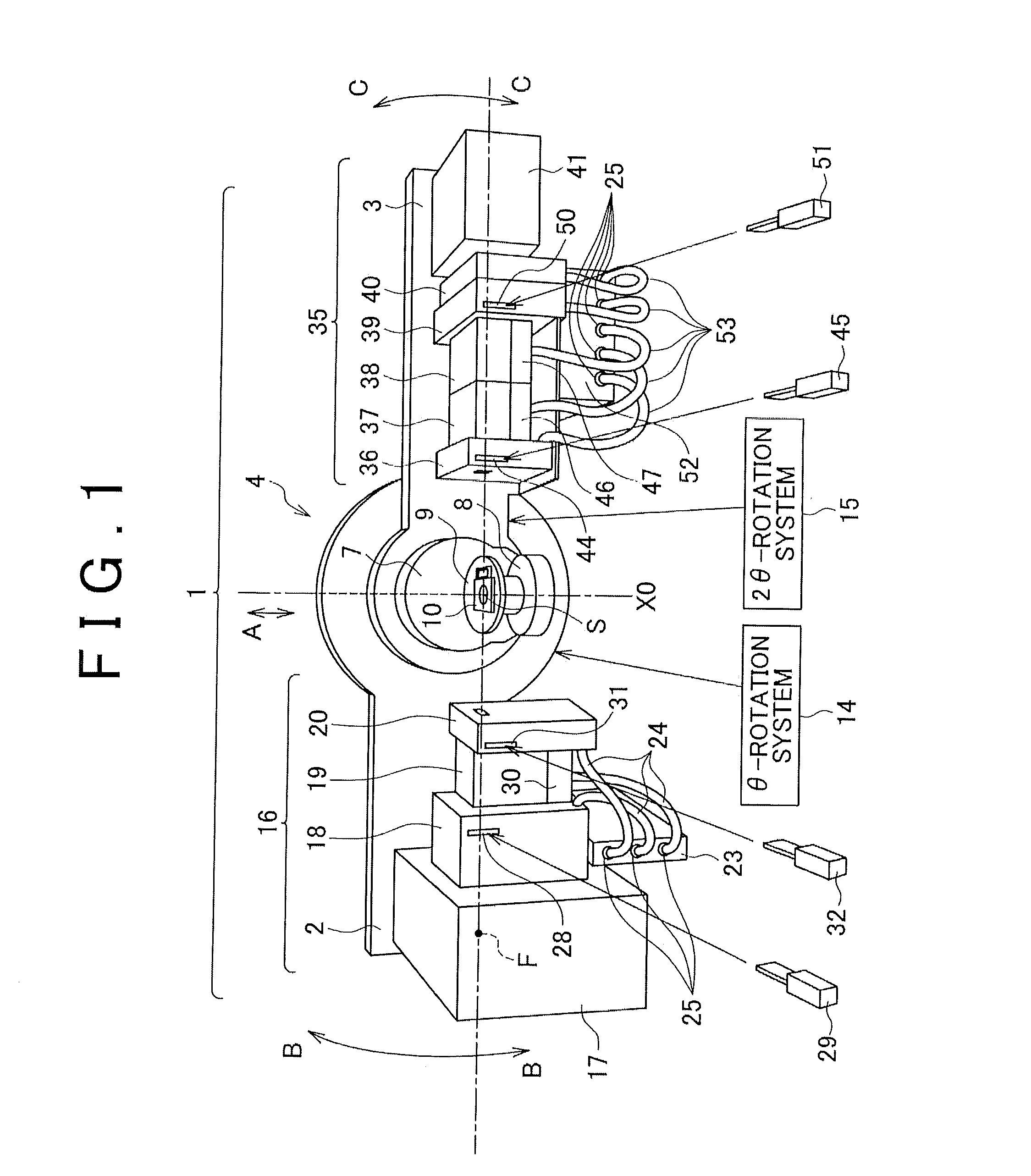
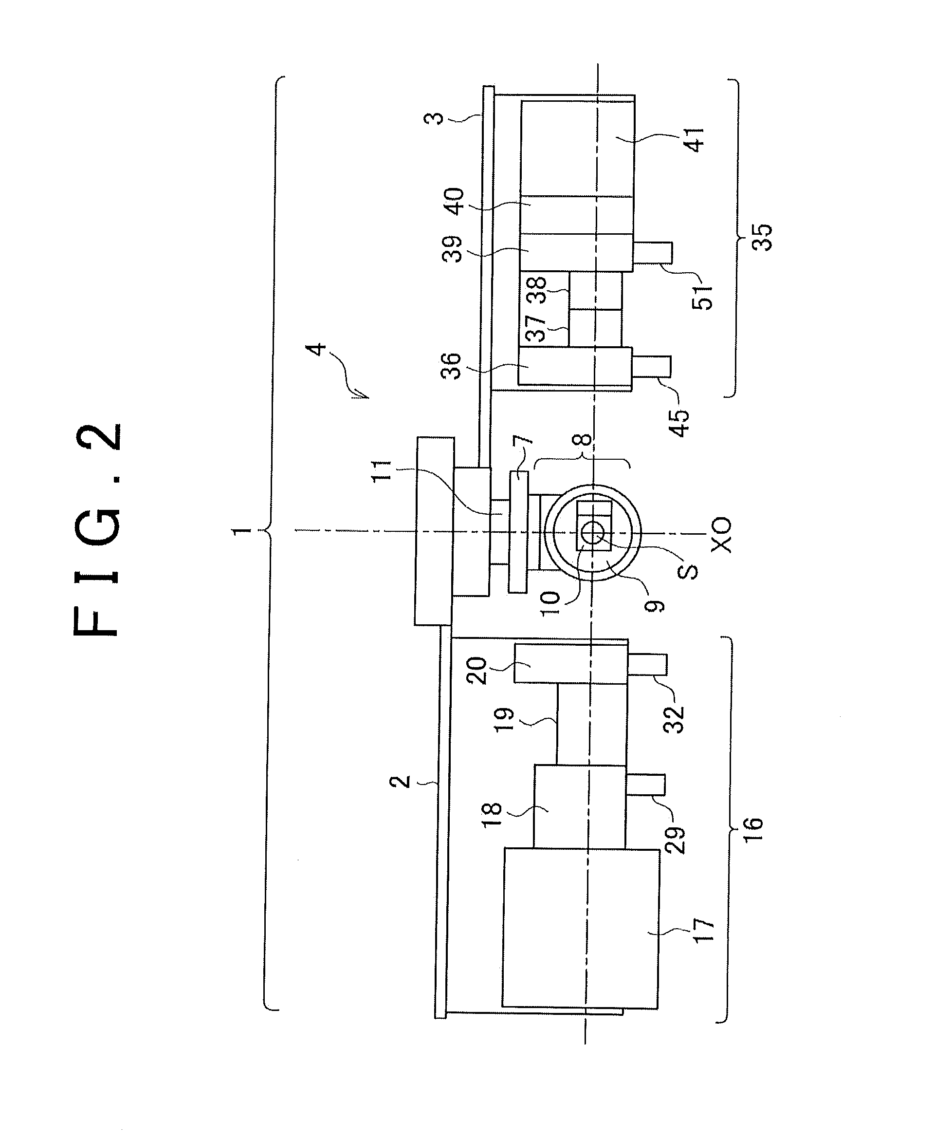
[0037]FIGS. 1 and 2 chow an embodiment of the X-ray analyzer according to the present invention. The X-ray analyzer 1 shown herein has a goniometer (angle measuring device) 4 having an incidence-side arm 2 and a receiving-side arm 3. A Z-axis stage 7 is attached to a center portion of the goniometer 4. A specimen support 8 is attached to the Z-axis stage 7. A specimen plate 9 is attached to the specimen support 8. A specimen S as a measurement subject is filled into a specimen holder 10. The specimen holder 10 is placed on the specimen plate 9. The Z-axis s...


PUM

PropertyMeasurementUnit
voltageaaaaaaaaaa
distanceaaaaaaaaaa
timeaaaaaaaaaa

Abstract

An X-ray optical component device having an X-ray optical component unit, a motor controller, and a connector. The connector has motor pins and motor terminals electrically connected to a motor when engaged with each other, and a signal pin and signal terminal for sensing detachment of the connector, the signal pin and signal terminal being capable of engaging with each other. A pin-side connector and a terminal-side connector are detachable. When the pin-side connector is detached from the terminal-side connector, the time that the signal pin is removed from the signal terminal is earlier than the time that the motor pins are removed from the motor terminals. During replacement of an X-ray optical component unit equipped with a motor for adjusting the position of an X-ray optical component, unwanted movement of the position of the X-ray optical component provided in the unit is prevented.

Description

TECHNICAL FIELD[0001]The present invention relates to an X-ray optical component device in which an X-ray optical component such as a monochromator or the like is connected to a controller by a connector. The present invention also relates to an X-ray analyzer that uses the X-ray optical component device.BACKGROUND ART[0002]The apparatus disclosed in Patent Citation 1 is known as a conventional X-ray analyzer that uses an X-ray optical component device. A slit, a monochromator, or the like is cited as an example of the X-ray optical component in this X-ray analyzer. In Patent Citation 1, a unit referred to as a box, an adapter, or the like is used as an X-ray optical component unit provided with the X-ray optical component. A configuration is adopted in which an X-ray optical component unit such as a box, and adapter, or the like is mounted to and dismounted from a goniometer, which is an angle measuring device.[0003]Various types of X-ray optical component units are prepared accord...

Claims


Application Information

Patent Timeline
Patent Type & Authority Applications(United States)
IPC IPC(8): G21K1/00G01N23/083
CPCG01N23/083G21K1/00G21K1/06
Inventor WAKASAYA, KENJIOZAWA, TETSUYA
Owner RIGAKU CORP
Why Eureka
Try Eureka