Method and system for controlling a turbocompressor group

a turbocompressor and group technology, applied in the direction of machines/engines, mechanical apparatus, engine starters, etc., can solve the problems of cyclical delivery and backflow of compressed medium, rapid temperature rise, and pressure, so as to prevent unwanted change of total process variables

Inactive Publication Date: 2014-02-11
MAN ENERGY SOLUTIONS SA
View PDF7 Cites 0 Cited by
  • Summary
  • Abstract
  • Description
  • Claims
  • Application Information

AI Technical Summary

Benefits of technology

[0019]According to the present invention, it is now provided that the distance to be maintained by at least one control device is trimmed relative to its first distance based on the trimming of the other control devices in such a way that a total process variable remains substantially constant. Accordingly, by taking into account the trimming of the other control devices, an unwanted and disadvantageous change in a total process variable, for example, a total flow rate, a total flow capacity, a total suction pressure and / or a total final pressure and / or a total pressure ratio, can be prevented by the trimming of a control device.
[0020]If three or more turbocompressors are connected together, for example, three compressors operating in parallel or two compressors connected in series which, as a totality, operate in parallel with a third compressor, a group of this kind has more degrees of freedom. Therefore, one or more control devices can be trimmed. Further, if the rest of the control devices are trimmed according to the invention based on the trimming of the trimmed control devices, an unwanted change in a total process variable can be prevented.

Problems solved by technology

Surging occurs when the operating point of the turbocompressor enters the unstable region of the performance map due to a reduction in the flow rate or an increase in the pressure ratio.
This results in cyclical delivery and backflow of the compressed medium, often accompanied by high vibrations, pressure surges, and a rapid rise in temperature in the turbocompressor.
Possible consequences are, for example, bearing damage, rubbing damage, and damage to the impeller or impeller vanes, which could lead to operating failure.
Without any coordination of these control devices, an uneven load sharing may come about between the individual turbocompressors, and the entire system can become unstable due to control devices acting counter to one another.
However, while the known load sharing control selects substantially the same distance from the respective surge limit curve for all of the turbocompressors in such a way that the interconnected compressors, as a totality, present the desired total process variables, for example, a total flow capacity and a total pressure ratio, manual trimming of individual control devices without taking into account the rest of the turbocompressors leads to an unwanted change in these total process variables.
For example, if the distance from the surge limit of only one compressor of a group of two turbocompressors is reduced, this leads to a reduction in its flow capacity with the pressure ratio remaining the same and, therefore, also to an unwanted reduction in the total flow capacity of the group.

Method used


Image

  • Method and system for controlling a turbocompressor group
  • Method and system for controlling a turbocompressor group

Examples


Embodiment Construction

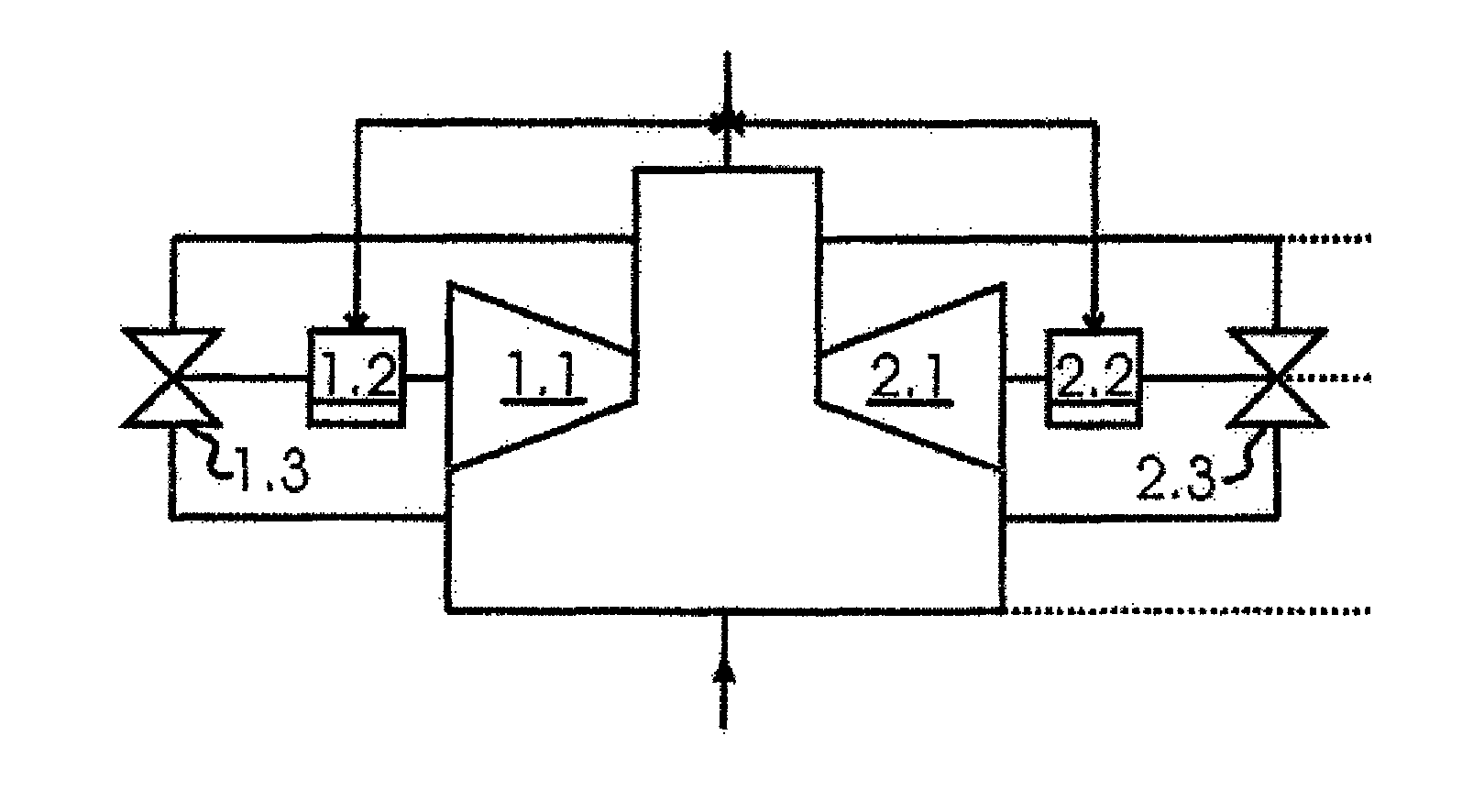
[0027]FIG. 1 shows a group of two turbocompressors 1.1, 2.1 which are connected in parallel. Every turbocompressor has a control device 1.2 and 2.2 for maintaining a distance from a surge limit curve P1 and P2, respectively, (FIG. 2) which, for example, changes a speed of a respective compressor and / or opens a relief valve 1.3 and 2.3, respectively, to maintain this distance. As is indicated by the double-arrow in FIG. 1, the two control devices 1.2, 2.2 communicate with one another and convey, particularly mutually, the distances to be maintained by them from the surge limit curve.

[0028]A method according to an embodiment of the present invention for controlling this group is described more fully with reference to FIG. 2.

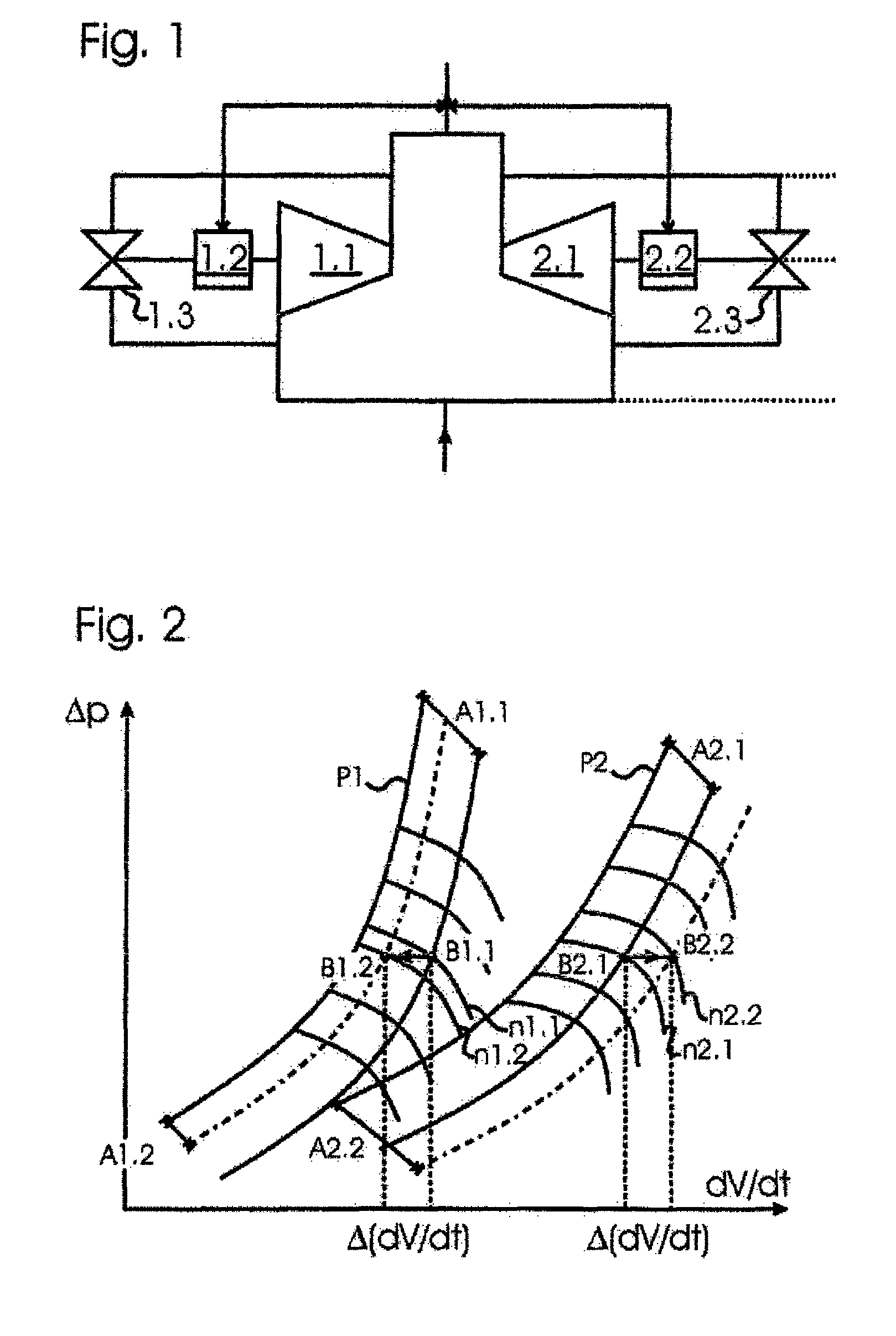
[0029]FIG. 2 shows the performance maps of the two turbocompressors 1.1, 2.1 in the form of a pressure ratio Δp over the flow capacity dV / dt. For this purpose, the surge limit curves P1 and P2, respectively, and some lines of constant speed n1.1, n1.2 and n2.1, n2....


PUM


Abstract

A method for controlling at least two turbocompressors (1.1, 2.1), each having a control device (1.2, 2.2) for maintaining a distance relative to a surge limit curve (P1, P2) of the respective turbocompressor; wherein a first distance (A1.1, A2.1) is determined for each turbocompressor from its surge limit curve; wherein the distance to be maintained can be trimmed relative to this first distance in the control devices; and wherein the distance (A2.2) of a control device (2.2) to be maintained is trimmed relative to its first distance (A2.1) based on a trimming (A1.1→A1.2) of another control device (1.2) in such a way that a total process variable (dV / dt) remains substantially constant.

Description

BACKGROUND OF THE INVENTION[0001]1. Field of the Invention[0002]The present invention is directed to a method of controlling two or more turbocompressors each having a control device for maintaining a distance of an operating point relative to the surge limit curve of the respective turbocompressor and to a system and a computer readable medium for implementing said method.[0003]2. Description of the Related Art[0004]The performance map of a turbocompressor is divided by the surge limit curve into a stable region and an unstable region. Surging occurs when the operating point of the turbocompressor enters the unstable region of the performance map due to a reduction in the flow rate or an increase in the pressure ratio. This results in cyclical delivery and backflow of the compressed medium, often accompanied by high vibrations, pressure surges, and a rapid rise in temperature in the turbocompressor. Possible consequences are, for example, bearing damage, rubbing damage, and damage ...

Claims


Application Information

Patent Timeline
Patent Type & Authority Patents(United States)
IPC IPC(8): F04D27/02
CPCF02B37/16F02B37/007F04D27/0284F04D25/16Y02T10/144F04D27/0269Y02T10/12
Inventor DIRKS, JURGENJANSEN, PETER
Owner MAN ENERGY SOLUTIONS SA
Why Eureka
Try Eureka