Method and system for controlling a turbocompressor group

一种涡轮压缩机、控制装置的技术,应用在计算机程序领域,能够解决没有控制装置微调等问题

Inactive Publication Date: 2010-07-14
MAN ENERGY SOLUTIONS SA
View PDF8 Cites 0 Cited by
  • Summary
  • Abstract
  • Description
  • Claims
  • Application Information

AI Technical Summary

Problems solved by technology

There is no targeted fine-tuning of the individual controls

Method used


Image

  • Method and system for controlling a turbocompressor group
  • Method and system for controlling a turbocompressor group
  • Method and system for controlling a turbocompressor group

Examples


Embodiment Construction

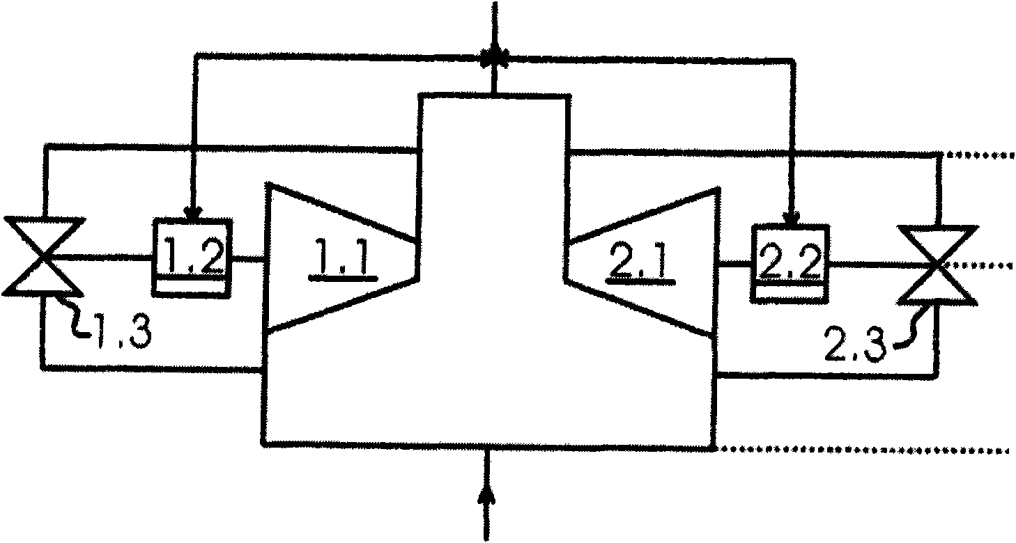
[0024] figure 1 A composite structure of two parallel-connected turbocompressors 1.1, 2.1 is shown. Each turbo compressor has a curve P1 or P2 ( figure 2 ) The control device 1.2 or 2.2 for maintaining the distance, the control device 1.2 or 2.2 for maintaining this distance, for example, changes the rotational speed of the corresponding compressor and / or opens the pressure reducing valve 1.3 or 2.3. as passed figure 1 As indicated by the dotted double arrow in , the two control devices 1.2, 2.2 communicate with each other and in particular communicate to each other the distance to be maintained by them relative to the surge limit curve.

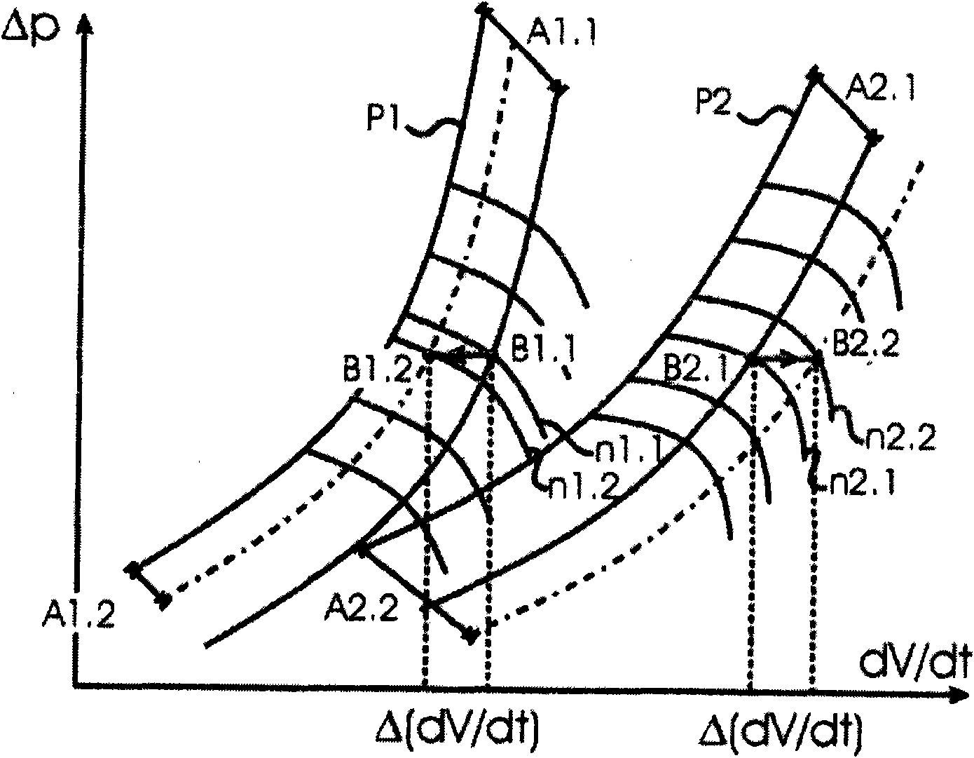
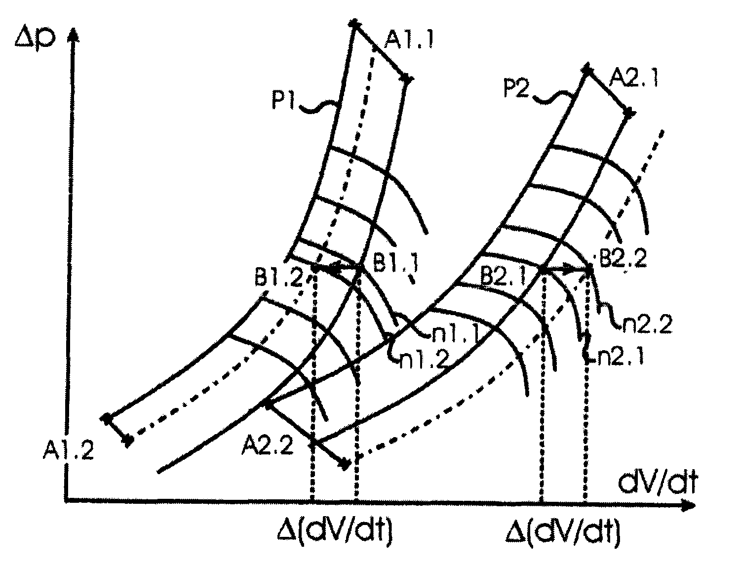
[0025] now by means of figure 2 A method for controlling such a composite structure according to an embodiment of the invention is explained in detail.

[0026] exist figure 2 , the combined characteristic curve in the form of the pressure ratio Δp of the two turbocompressors 1.1, 2.1 is shown with respect to the displacement dV / dt. ...


PUM


Abstract

The invention provides a method and a system for controlling a turbocompressor group. The method for controlling at least two turbocompressors (1.1, 2.1), each having a control device (1.2, 2.2) for maintaining a distance relative to a surge limit curve (P1, P2) of the respective turbocompressor; wherein a first distance (A1.1, A2.1) is determined for each turbocompressor from its surge limit curve; wherein the distance to be maintained can be trimmed relative to this first distance in the control devices; and wherein the distance (A2.2) of a control device (2.2) to be maintained is trimmed relative to its first distance (A2.1) based on a trimming (A1.1->A1.2) of another control device (1.2) in such a way that a total process variable (dV / dt) remains substantially constant.

Description

technical field [0001] The invention relates to a method for controlling two or more turbocompressors coupled in a composite structure according to the preamble of claim 1 and to a system and a computer program for implementing such a method . Background technique [0002] The combined characteristic curve of the turbo compressor is divided into a stable region and an unstable region by the surge limit curve. Surge occurs if the operating point of the turbocompressor enters the unstable region of the combined characteristic curve due to a reduction in the delivery volume or an increase in the pressure ratio. In this case, a cyclical feed and return flow of the compressed medium then occurs, which is often accompanied by high vibrations, pressure surges and rapid temperature rises in turbocompressors. Possible consequences are, for example, bearing damage, galling, impeller or blade damage, which can lead to a stoppage of work. [0003] To avoid this, control devices are k...

Claims


Application Information

Patent Timeline
Patent Type & Authority Applications(China)
IPC IPC(8): F04D27/02F04D25/16F04D29/66
CPCF04D27/0269F04D27/0284Y02T10/144F02B37/007F02B37/16F04D25/16Y02T10/12
Inventor J·德克斯P·詹森
Owner MAN ENERGY SOLUTIONS SA
Why Eureka
Try Eureka