Magneto-electric speed regulator

A speed governor, magnetoelectric technology, applied in the field of magnetoelectric combined speed control drive system, can solve the problems of eddy current thermal temperature rise, the overall efficiency is not high, increase, etc., to solve the temperature rise and efficiency problems, save energy Efficient effect

Inactive Publication Date: 2017-02-22
诸暨和创磁电科技有限公司
View PDF0 Cites 17 Cited by
  • Summary
  • Abstract
  • Description
  • Claims
  • Application Information

AI Technical Summary

Problems solved by technology

[0009] Based on the above-mentioned advantages and disadvantages of the disc structure and the double-tube structure, in the case of a certain magnetic field, in order to make more magnetic force lines pass through the conductor rotor and make the magnetic field coupling area larger, the conductor rotor adopts a double-tube structure. There is a layer of copper plate on the inner side of the cylinder and the outer wall of the inner cylinder, which surrounds the permanent magnet. The magnet acts on both sides, causing the copper conductor to generate eddy current, thereby generating an induced magnetic field. The induced magnetic field generated by this structure will be significantly larger than the previous two. Large, improved magnetic field strength and transmission torque, but the complex speed regulating mechanism has not changed
[0010] The common problem of the above three types of permanent magnet governors is that the temperature rise of the eddy current heat is too high when the slip rate is large, and the high power requires a complicated water cooling device, and the overall efficiency is not high

Method used


Image

  • Magneto-electric speed regulator
  • Magneto-electric speed regulator
  • Magneto-electric speed regulator

Examples


Embodiment 1

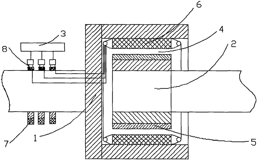
[0036] Reference attached figure 1 This embodiment discloses a magnetoelectric governor, which is characterized in that it includes a permanent magnet rotor 1 and an electromagnetic rotor 2, and also includes a current controller 3. Uniform and fixed circumferential air gap 4, the permanent magnet rotor 1 and the electromagnetic rotor 2 are concentrically installed and socketed, and the permanent magnet rotor 1 is inside, and its inner wall is provided with alternately arranged N and S poles. The permanent magnet 5, the electromagnetic rotor 2 is a salient pole armature on the outside. In the present invention, the excitation winding 6 is installed on the salient pole of the electromagnetic rotor 2, and the winding directions on the two adjacent iron cores of the same direction winding are opposite, so that the polarities of the magnetic poles generated by the adjacent iron cores are opposite, that is, the N and S poles are arranged alternately , the electromagnetic rotor 2 i...

Embodiment 2

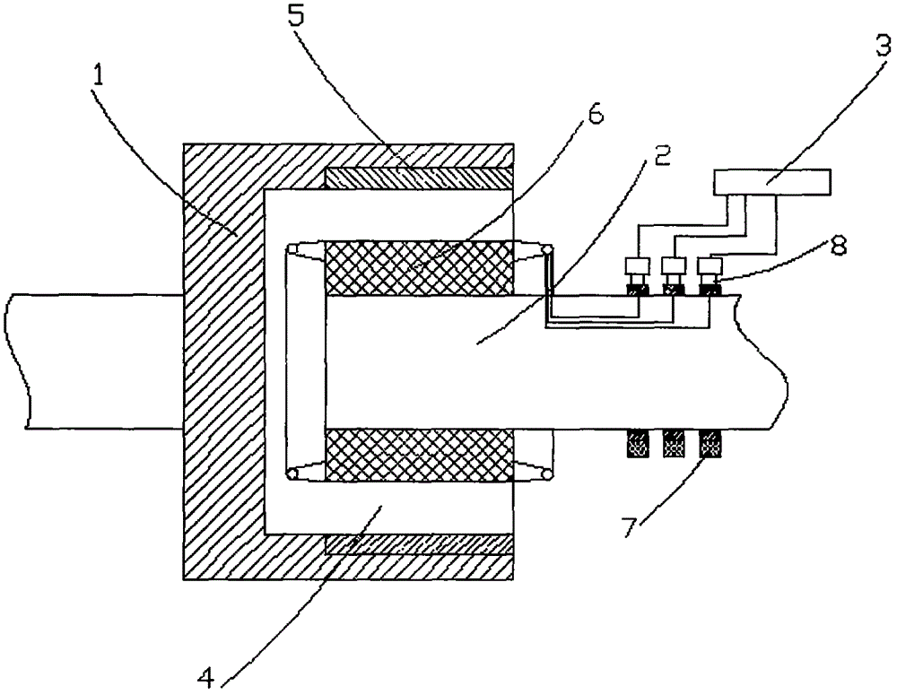
[0038] On the basis of Embodiment 1, this embodiment discloses a magnetoelectric speed governor, which is characterized in that it includes a permanent magnet rotor 1 and an electromagnetic rotor 2, and also includes a current controller 3. The permanent magnet rotor 1 and the A uniform and fixed circumferential air gap 4 is formed between the electromagnetic rotors 2. The permanent magnet rotor 1 and the electromagnetic rotor 2 are concentrically installed and socketed. The permanent magnet rotor 1 is outside, and N , permanent magnets 5 arranged alternately with S poles, and the electromagnetic rotor 2 is a salient pole armature inside.

Embodiment 3

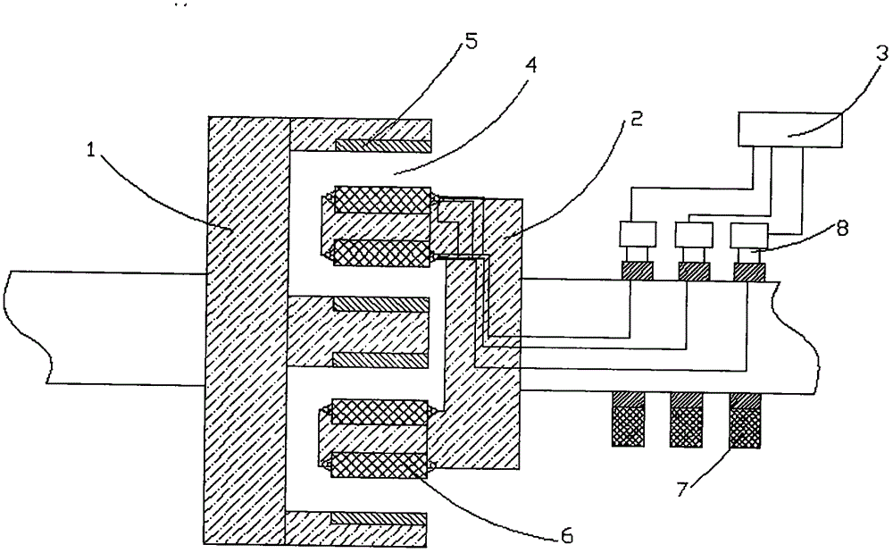
[0040] On the basis of Embodiment 1, this embodiment discloses a magnetoelectric speed governor, which is characterized in that it includes a permanent magnet rotor 1 and an electromagnetic rotor 2, and also includes a current controller 3. The permanent magnet rotor 1 and the A uniform and fixed circumferential air gap 4 is formed between the electromagnetic rotors 2. The permanent magnet rotor 1 is a double cylinder type, and the electromagnetic rotor 2 is concentrically installed and sleeved between the two cylinders of the permanent magnet rotor 1. The permanent magnets 5 arranged alternately with N and S poles are arranged on both cylinders of the permanent magnet rotor 1, and the electromagnetic rotor 2 is a salient pole armature.


PUM


Abstract

The invention discloses a magneto-electric speed regulator. The magneto-electric speed regulator comprises a permanent-magnet rotor and an electric-magnetic rotor and also comprises a current controller, wherein a uniform and fixed circumferential air gap is formed between the permanent-magnet rotor and the electric-magnetic rotor. By the magneto-electric speed regulator, speed regulation can be achieved on the condition of fixing the air gap, excessively large eddy current can be fed back to power utilization equipment or a power grid, and the problems of temperature rise and efficiency are solved.

Description

technical field [0001] The invention relates to a mechanical power transmission system, in particular to a magnetoelectric combined speed regulation driving system. Background technique [0002] Hydraulic coupling speed regulation and AC frequency conversion speed regulation have gained mature experience in mechanical speed regulation, but there are still some problems. The invention of permanent magnet eddy current speed control expands a new field for industrial speed control. It directly adjusts the speed of the load, the motor speed remains unchanged, the load of the system, such as pressure or flow, is sent a feedback signal by the sensor, and the actuator is controlled by PLC to adjust the magnetic field gap or coupling area, and the speed of the load changes. [0003] At present, there are three types of permanent magnet eddy current governors used at home and abroad. [0004] (1) Axial type (disc type) [0005] The axial force is balanced by adopting double perman...

Claims


Application Information

Patent Timeline
Patent Type & Authority Applications(China)
IPC IPC(8): H02K49/00H02K49/10
CPCH02K49/00H02K49/106
Inventor 李和良杨湜邰建锋
Owner 诸暨和创磁电科技有限公司
Why Eureka
Try Eureka