
Optical thread position detection device

A detection device, detection device technology, applied in the direction of using optical devices, measuring devices, instruments, etc., can solve the problems of error sources, expensive manufacturing or acquisition, etc., achieve rapid activation, avoid waiting time, and simple production

Active Publication Date: 2012-07-04
KRONES AG
View PDF6 Cites 5 Cited by
  • Summary
  • Abstract
  • Description
  • Claims
  • Application Information

AI Technical Summary

Problems solved by technology

The camera would have to be rotated or use two parts, for example using two cameras, which brings additional costs
[0008] In addition, the exposure of the camera takes place on a reduced star wheel, thus creating an additional source of error due to transmission
Of all the different methods described so far, that is to say mechanical and optical inspection methods, the marking of at least one kind of indentation or elevation of the parison requires special preforms, which are more complex than the manufacture of standard preforms. or get significantly more expensive

Method used


Image

  • Optical thread position detection device
  • Optical thread position detection device
  • Optical thread position detection device

Examples


Embodiment Construction

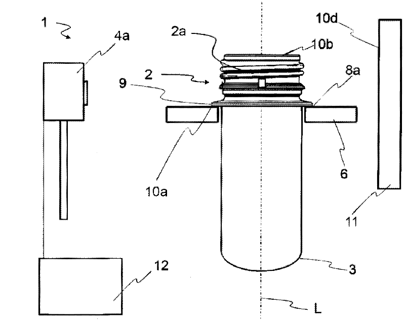
[0062] figure 1 It is an optical thread position detecting device according to the present invention.

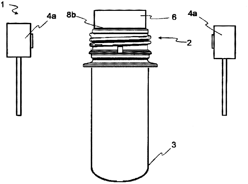
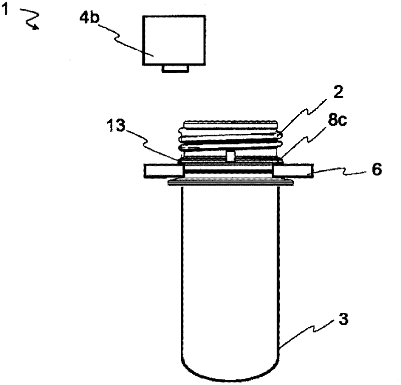
[0063] The optical thread detection device 1 comprises a detector 4a for recording an image or video. The detector 4a is more preferably an imaging device 4a, but it can also include direct or indirect lighting equipment for the parison 3. It is also applicable to add a lighting device in the area of ​​the detector 4a, so that it can be used for the container from the same direction of taking pictures. Mouth lighting. In addition, the lighting device can be a flash memory device, and the camera device 4a is used to store the image of the thread 2 , especially the image of the threaded part 2a of the container 3 . The registered images are preferably evaluated in the processor device 12 .

[0064] The image or image information registration is preferably expressed perpendicular to the long axis L of the container 3 , and can also be recorded at an angle of 0-90° to the lon...


PUM


Abstract

The invention relates to an optical thread position detection device (1) for detecting the rotational position of threads (2) of containers (3). The thread position detection device (1) comprises at least an optical detector (4a, 4b) and a positioning device (6) for the defined orientation of a longitudinal axis (L) of the containers (3) relative to the detector (4a,b), the positioning device (6) and a defined coupling area (8a,b,c) of the container (3) being connectable to one another. According to the invention the optical detector (4a,b), without coming into contact, registers items of information on at least one relative rotational position of at least one thread portion (2a), the processor device serving to generate data on the rotational position of the container, incorporating a defined reference variable and the items of information.

Description

technical field [0001] The invention relates to the field of photoelectric detection, in particular to an optical thread position detection device. Background technique [0002] The invention relates to an optical thread position detection device according to claim 1 and a method for optical detection of the thread position of a container according to claim 10 . [0003] For containers where the neck (and thread) must be in a specific position relative to the shape of the blown bottle, there are currently many mechanical and optical solutions with specific markings such as indentations on the parison (neck) or gap. Orientation of parisons or preforms is necessary, especially for containers manufactured by "selective heating" exposure to heat or a similar light source) enables the desired temperature profile to be applied purposefully to the parison body. [0004] In mechanical solutions, wedges or similar shapes are used to insert gaps (preform indentations), thereby repa...

Claims


Application Information

Patent Timeline
Patent Type & Authority Applications(China)
IPC IPC(8): G01B11/00B29C49/78
CPCG01B11/26G01B11/00
Inventor 杰拉尔德·休特纳斯特凡·皮亚纳罗伯特·施密特乌尔里希·拉普格尔哈特·菲斯克
Owner KRONES AG
Learn More